background image

34

Installation advice

Touch-control ceramic hobs are particularly sensitive
electrical appliances.
Leaving aside the end result, these hobs, produced by
a specific technique, are completely different from
conventional hobs.

Since the electronic equipment is extremely sensitive,
special care must be taken when installing the hob,
which will be affected by knocks or humidity.

Moreover, because of their special structure touch-
control hobs have a built-in installation height which
exceeds 

40 mm

 the standard maximum thickness of

ordinary hobs.

The unit below the hob has to be modified during built-
in installation and assembly.
To allow built-in installation, the engineer must remove
the front and rear stabilizer cross-pieces at each end of
the wooden unit.
Since this unit is often installed between other units, its
stability is not impaired.
However, this modification is not possible on all units.
Corner units, for example, usually have a swivel body
fixed at the bottom and top by means of a beam.
In this case, the top part cannot be removed because
the swivel body might fall if disconnected from the
stabilizer.

There may also be problems in installation if the unit
below the hob contains a built-in appliance which uses
water or produces steam (refrigerators, dishwashers,
washing machines and some types of oven).
Experience has shown that the heat generated between
the appliance and the hob without ventilation will cause
condensation which damages the hob.

Summary of Contents for SE 2741

Page 1: ...VES TOUCH CONTROL CERAMIC HOBS GLASKERAMIKKOCHFELDER MIT TASTENBEDIENUNG ENCIMERAS VITROCERAMICAS SENSORIALES GLASKERAMISCHE KOOKPLATEN TIPTOETSEN Istruzioni per l uso Mode d emploi Instructions for use Bedienungsanleitung Instrucciones de uso Gebruiksaanwijzing ...

Page 2: ...Pagina 1 15 Page 17 31 Page 33 47 Seite 49 63 Página 65 79 Bladzijde 81 95 ...

Page 3: ...37 Using the hob 39 Touch control keys 39 Switching on the cooking zones 41 Control disabling key 42 Switching off the cooking zones 42 Safety cut out device 43 Residual heat indicator 43 Practical hints for use of the cooking zones 43 General advice 44 Controls 44 Warnings 44 Cleaning maintenance and suggestions 46 ...

Page 4: ...allow built in installation the engineer must remove the front and rear stabilizer cross pieces at each end of the wooden unit Since this unit is often installed between other units its stability is not impaired However this modification is not possible on all units Corner units for example usually have a swivel body fixed at the bottom and top by means of a beam In this case the top part cannot b...

Page 5: ... automatically activated Numbers 1 to 9 appear in sequence above the symbols and When they go out the appliance is ready for use Positioning This ceramic hob can be installed in units of all kinds in brickwork metal wood wood clad with melamine laminates or plywood The opening for built in installation must be of the dimensions shown ...

Page 6: ...ear edge of the unit and 110 mm from the left hand side The hob is complete with a special adhesive seal A which prevents any infiltration into the unit The seal must be carefully fixed around the edge of the opening for built in mounting pressing lightly with the hand to ensure that it sticks Remove the paper protection and place the hob on the seal The seal guarantees a waterproof finish and a p...

Page 7: ...er with minimum distance between contacts at least 3 mm on the appliance power supply line at a point easily reached from the appliance The options for connection to the electrical mains are indicated in the tables below or on the data plate underneath the hob Cables H 05 RRF H 05 RNF 230V 400V 3N 400V 2N Minimum gauge in mm 2 2 5 1 5 2 5 To access the terminal board press the two side tabs as ind...

Page 8: ...e lid has been fixed back in place and ensure that the earth connection is in good working order N B NEVER TOUCH THE ELECTRONIC CIRCUIT BOARD IN ANY CIRCUMSTANCES Our company declines any responsibility for injury or damage deriving from failure to make the earth connection or inadequate connection to earth ...

Page 9: ...tip will activate the corresponding command The appliance will recognize your request and give a short beep Touch control keys see page 40 Mod SE 2741 Mod SE 2752 1 Front left hand cooking zone 210 120 1400 700W 210 120 1400 800W 2 Back left hand cooking zone 145 1200W 145 1200W 3 Back right hand cooking zone 180 1800W 170 x265 1400 800W 4 Front right hand cooking zone 145 1200W 180 1800W 5 Dual c...

Page 10: ...40 ...

Page 11: ... area is activated at maximum power Within 15 seconds during which time the 9 continues to flash it is possible to take advantage of the automatic heating function Press the key until the required power is reached The set value flashes for a while during which time the cooking area will operate at maximum power When the number stops flashing power reduces to the selected level The following table ...

Page 12: ...oking zones a blinking letter H will appear on the displays above the and buttons residual heat Control disabling key The control disabling key prevents any accidental operations while the hob is in use The controls can be disabled during use although operations already in progress continue and the relative settings can still be adjusted To disable the controls Press the key the lights beside the ...

Page 13: ...of the cooking zones High heat values are necessary in the following cases considerable quantities of food to be cooked cooking in pans without lids use of glass or ceramic casserole dishes However only daily use will teach you the best settings for your own cooking habits Table for use of cooking zones Heat setting 1 2 3 4 5 6 7 8 9 VERY LOW LOW SLOW MEDIUM HIGH VERY HIGH Heating and keeping read...

Page 14: ...beeper will warn the user Warning should an excessive quantity of liquid boil over and cover the control keys the sensorial surface automatically switches off and must be cleaned before being switched on again The controls should also be disabled to prevent accidental switch on by small children pets long periods out of use etc N B to prevent the glass overheating each zone is equipped with a temp...

Page 15: ...off an acrid smell or a smell of burning which will disappear completely in a few minutes For good efficiency and minimum energy consumption use only casserole dishes and pans suitable for electric hobs i e with perfectly flat bottoms Pan bottoms must at least be as large in diameter as the ring marked on the glass If they are smaller energy will be wasted and so larger pans should be used The pan...

Page 16: ...an be removed by cleaning the hob with vinegar 2 Never spill sugar on the hob while cooking if this happens by accident switch off the hob immediately and clean the part affected with the scraper or with hot water before the zone cools and dry with a cloth If the glass is not cleaned immediately the sugar may form deposits which are impossible to remove 3 Any burnt residues left on the cooking zon...

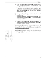
Page 17: ...he glass hob should not be used as a work top Grains of sand from vegetables for example may accidentally stick to the bottom of a pan and leave scratches on the hob 7 In case of any malfunction such as overheating or inadequate heating of a zone contact the after sales service as soon as possible Our company declines any responsibility in case of damage to the glass due to failure to comply with ...

Reviews: