background image

Installation

65

EN

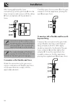
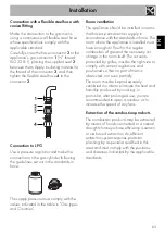
Connection with a flexible steel hose with 
conical fitting

Make the connection to the gas mains 
using a continuous wall flexible steel hose 
whose specifications comply with the 
applicable standard.
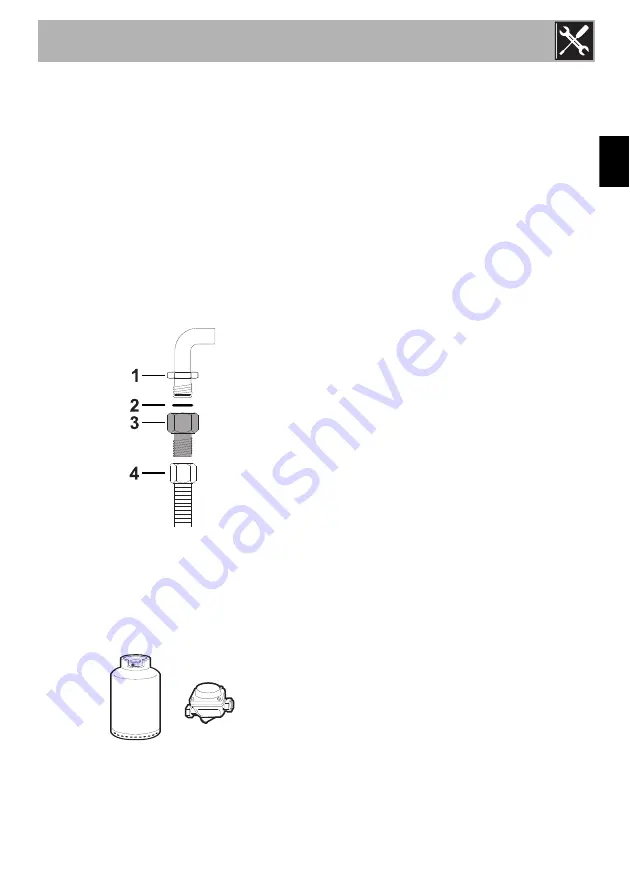
Carefully screw the hose connector 

3

 to the 

appliance’s gas connector 

1

 (½” thread 

ISO 228-1), placing the supplied seal 

2


between them. Apply insulating material to 
the thread of the connector 

3

, and then 

tighten the flexible steel hose 

4

 to the 

connector 

3

.

Connection to LPG

Use a pressure regulator and make the 
connection on the gas cylinder following 
the guidelines set out in the standards in 
force.

The supply pressure must comply with the 
values indicated in the table in “Gas types 
and Countries”.

Room ventilation

The appliance should be installed in rooms 
that have a permanent air supply in 
accordance with the standards in force. The 
room where the appliance is installed must 
have enough air flow for the regular 
combustion of gas and the necessary air 
change in the room itself. The air vents, 
protected by grilles, must be the right size to 
comply with current regulations and 
positioned so that no part of them is 
obstructed, not even partially.
The room must be kept adequately 
ventilated in order to eliminate the heat and 
humidity produced by cooking: in 
particular, after prolonged use, you are 
recommended to open a window or to 
increase the speed of any fans.

Extraction of the combustion products

The combustion products may be extracted 
by means of hoods connected to a natural 
draught chimney whose efficiency is certain 
or via forced extraction. An efficient 
extraction system requires precision 
planning by a specialist qualified in this 
area and must comply with the positions 
and distances indicated by the applicable 
standards. 

Summary of Contents for TR90BL

Page 1: ...orage compartment 50 3 5 Using the hob 50 3 6 Using the oven 51 3 7 Cooking advice 53 3 8 Programmer clock 54 4 Cleaning and maintenance 58 4 1 Instructions 58 4 2 Cleaning the appliance 58 4 3 Removing the door 59 4 4 Cleaning the door glazing 60 4 5 Cleaning the inside of the oven 60 4 6 Extraordinary maintenance 61 5 Installation 63 5 1 Gas connection 63 5 2 Adaptation to different types of gas...

Page 2: ...blanket or other appropriate cover The appliance must never be cleaned by unsupervised children Have qualified personnel carry out installation and assistance interventions according to the standards in force Do not modify this appliance Do not insert pointed metal objects cutlery or utensils into the slots in the appliance Do not try to repair the appliance yourself or without the intervention of...

Page 3: ...ification plate for any reason 1 3 Manufacturer liability The manufacturer declines all liability for damage to persons or property caused by use of the appliance other than the one envisaged non observance of the user manual provisions tampering with any part of the appliance use of non original spare parts 1 4 Appliance purpose This appliance is intended for cooking food in the home environment ...

Page 4: ...r manual carefully before using the appliance 1 7 How to read the user manual This user manual uses the following reading conventions 1 Use instruction sequence Single use instruction Plastic packaging Danger of suffocation Do not leave the packaging or any part of it unattended Do not let children play with the packaging plastic bags Instructions General information on this user manual on safety ...

Page 5: ...tion 1 Backguard 2 Cooking hob 3 Control panel 4 Oven light 5 Seal 6 Door 7 Fan 8 Storage compartment Rack tray support frame shelf 2 2 Cooking hob AUX Auxiliary SR Semi rapid R Rapid UR2 int internal crown ultra rapid UR2 est external crown ultra rapid ...

Page 6: ...constant 3 Function knob The oven s various functions are suitable for different cooking modes After selecting the required function set the cooking temperature using the temperature knob 4 Hob burner knobs Useful for lighting and adjusting the hob burners Press and turn the knobs anti clockwise to the value to light the relative burners Turn the knobs to the zone between the maximum and minimum s...

Page 7: ...ooking The fan causes a steady outflow of air from above the door which may continue for a brief period of time even after the appliance has been turned off Interior lighting The internal light of the ovens comes on when any function is selected 2 5 Available accessories Reduction pan stand Useful when using small cookware WOK reduction pan stand Useful when using a wok Rack Useful for supporting ...

Page 8: ...pport the rotisserie rod Rotisserie handle Useful for taking the rotisserie rod out of the oven Self cleaning panels Useful for absorbing small grease residues The accessories intended to come into contact with food are made of materials that comply with the provisions of current legislation Supplied and optional accessories can be requested to Authorised Assistance Centres Use only original acces...

Page 9: ...er use Risk of damage to surfaces Do not cover the bottom of the oven cavity with aluminium or tin foil sheets If you wish to use greaseproof paper place it so that it will not interfere with the hot air circulation inside the oven Do not place pans or trays directly on the bottom of the oven cavity Do not use the open door to rest pans or trays on the internal glass pane Do not pour water directl...

Page 10: ... back Tray rack The tray can be used two different ways Inside the rack with the anti tip stop facing upwards to collect grease during cooking Resting on the rack with the anti tip stop facing downwards to cook sweets biscuits pastries etc High temperature inside the oven during use Danger of fire or explosion Do not spray any spray products near the oven Do not use or leave flammable materials ne...

Page 11: ...nects with the rotisserie motor Make sure that the contoured part is placed correctly on the guide frame and remove the handle 4 To activate the rotisserie turn the function knob to position 5 At the end of cooking use the rotisserie handle provided to extract the rod from the hole and remove the frame in order to take the rotisserie rod out of the oven cavity Grill rotisserie cooking must never e...

Page 12: ...ectronic ignition device Simply press the knob and turn it anti clockwise to the maximum flame symbol until the burner lights If the burner does not light in the first 15 seconds turn the knob to and wait 60 seconds before trying again After lighting keep the knob pressed in for a few seconds to allow the thermocouple to heat up The burner may go out when the knob is released in this case the ther...

Page 13: ...Select the temperature using the temperature knob Functions list Cookware diameters Auxiliary 12 14 cm Semi rapid 16 24 cm Rapid 18 26 cm Ultra rapid 18 28 cm Eco Using the grill and the lower heating element in combination is particularly suitable for cooking on a single shelf as it provides low energy consumption Ideal for cooking meat fish and vegetables Not recommended for desserts which must ...

Page 14: ...bination of the fan and the circulaire heating element incorporated in the rear of the oven allows you to cook different foods on several levels as long as they need the same temperatures and same type of cooking Hot air circulation ensures instant and even distribution of heat It will be possible for instance to cook fish vegetables and biscuits simultaneously on different levels without odours a...

Page 15: ...unction we recommend that you turn the temperature knob to the maximum value near the symbol to optimise cooking Foods should be seasoned before cooking Foods should also be coated with oil or melted butter before cooking Use the oven tray on the first bottom shelf to collect fluids produced by grilling Grilling processes should never last more than 60 minutes Advice for cooking desserts pastries ...

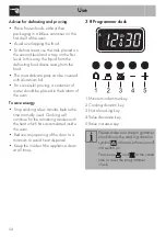
Page 16: ...d be placed in the bottom of the oven To save energy Stop cooking a few minutes before the time normally used Cooking will continue for the remaining minutes with the heat which has accumulated inside the oven Reduce any opening of the door to a minimum to avoid heat dispersal Keep the inside of the appliance clean at all times 3 8 Programmer clock 1 Minute minder timer key 2 Cooking duration key ...

Page 17: ...e display 4 At the end of cooking the heating elements will be deactivated On the display symbol turns off symbol flashes and the buzzer sounds 5 To turn off the buzzer just press any key of the programmer clock 6 Press keys and at the same time to reset the programmer clock Programmed cooking 1 Set the cooking time as described in the previous point Timed cooking 2 Press The sum of the current ti...

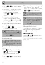
Page 18: ... required minutes 3 Wait approx 5 seconds without pressing any key to finish setting the minute minder The current time and the symbols and appear on the display Adjusting the buzzer volume The buzzer volume can be set to 3 different levels When the buzzer is in operation press to change the setting Deleting the set data Press keys and at the same time to reset the programs set Then switch off the...

Page 19: ...bs 1 5 Fan with grill 4 240 10 10 Bacon 0 7 Grill 5 240 7 8 Pork fillet 1 5 Fan with grill 4 240 10 5 Beef fillet 1 Grill 5 240 10 7 Salmon trout 1 2 Turbo Fan assisted 2 150 160 35 40 Monkfish 1 5 Turbo Fan assisted 2 160 60 65 Turbot 1 5 Turbo Fan assisted 2 160 45 50 Pizza 1 Turbo Fan assisted 2 260 8 9 Bread 1 Circulaire 2 190 200 25 30 Focaccia 1 Turbo Fan assisted 2 180 190 20 25 Bundt cake ...

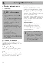
Page 20: ...ght damage the enamel lining of the oven Cooking hob grids Remove the grids and clean them with lukewarm water and non abrasive detergent Make sure to remove any encrustations Dry them thoroughly and return them to the hob Improper use Risk of damage to surfaces Do not use steam jets for cleaning the appliance Do not use cleaning products containing chlorine ammonia or bleach on steel parts or par...

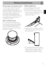
Page 21: ...s and thermocouples must always be perfectly clean Check them frequently and clean them with a damp cloth if necessary Remove any dry residues with a wooden toothpick or a needle 4 3 Removing the door For easier cleaning the door can be removed and placed on a canvas To remove the door proceed as follows 1 Open the door completely and insert two pins into the holes on the hinges indicated in the f...

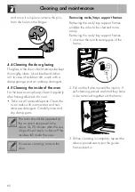
Page 22: ...and non abrasive detergent Carefully rinse and dry damp parts Removing racks trays support frames Removing the rack tray support frames enables the sides to be cleaned more easily Removing the rack tray support frames 1 Unscrew the two fastening pins of the frame 2 Pull out the frame toward the interior If self cleaning panels are fitted they have to be removed together wit the frame 3 When cleani...

Page 23: ... hour 3 If the panels are particularly dirty after the regeneration cycle remove them and wash them with neutral washing up liquid Rinse and dry them Put the panels back in the oven and set a fan assisted function at a temperature of 180 C for one hour in order to ensure that they are thoroughly dry 4 6 Extraordinary maintenance Replacing the internal light bulb 1 Completely remove all accessories...

Page 24: ...port Removing the seal of the oven To permit thorough cleaning of the oven the door seal may be removed There are fasteners on all 4 sides and in the middle to attach it to the edge of the oven Pull the seal outwards at the indicated points in order to remove it from the appliance To keep the seals clean use a non abrasive sponge and lukewarm water Seals should be soft and elastic Do not touch the...

Page 25: ...st its expiry date serigraphed on the hose itself Make the connection to the gas mains using a rubber hose whose specifications comply with current standards verify that the reference standard is stamped on the hose Carefully screw the hose connector 3 to the appliance s gas connector 1 thread ISO 228 1 placing the seal 2 between them The hose connector 4 can also be screwed to the hose connector ...

Page 26: ...acing the seal 2 between them Connection with a flexible steel hose with bayonet fitting Carry out the connection to the gas mains using a flexible steel hose with bayonet fitting compliant with B S 669 Apply insulating material to the thread of the gas hose connector 4 and then tighten the adapter 3 Screw the assembly to the movable connector 1 of the appliance placing the supplied seal 2 between...

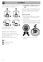
Page 27: ...t have a permanent air supply in accordance with the standards in force The room where the appliance is installed must have enough air flow for the regular combustion of gas and the necessary air change in the room itself The air vents protected by grilles must be the right size to comply with current regulations and positioned so that no part of them is obstructed not even partially The room must...

Page 28: ...rs through wall Air Combustion products Extractor fan 5 2 Adaptation to different types of gas In case of operation with other types of gas the burner nozzles must be changed and the minimum flame adjusted on the gas taps Replacing nozzles 1 Remove the pan stands burner caps and flame spreader crowns to access the burner casings 2 Replace the nozzles using a 7 mm socket wrench according to the gas...

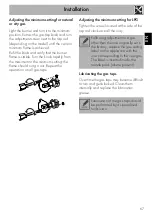
Page 29: ... go out Repeat the operation on all gas taps Adjusting the minimum setting for LPG Tighten the screw located at the side of the tap rod clockwise all the way Lubricating the gas taps Over time the gas taps may become difficult to turn and get blocked Clean them internally and replace the lubrication grease Following adjustment to a gas other than the one originally set in the factory replace the g...

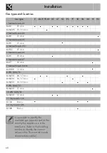
Page 30: ...ar 6 Natural Gas G27 G27 20 mbar 7 Natural Gas G2 350 G2 350 13 mbar 8 LPG G30 31 G30 31 28 37 mbar G30 31 30 37 mbar G30 31 30 30 mbar 9 LPG G30 31 G30 31 37 mbar 10 LPG G30 31 G30 31 50 mbar 11 City Gas G110 G110 8 mbar 12 City Gas G120 G120 8 mbar It is possible to identify the available gas types based on the country the appliance is to be installed in Refer to the heading number to identify t...

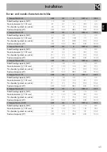
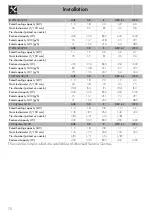
Page 31: ...00 500 800 400 1600 4 Natural Gas G25 1 AUX SR R UR2 int UR2 Rated heating capacity kW 1 1 1 8 3 0 1 0 4 0 Nozzle diameter 1 100 mm 77 100 134 80 155 Pre chamber printed on nozzle F1 Y F3 H1 H4 Reduced capacity W 400 500 800 400 1600 5 Natural Gas G25 AUX SR R UR2 int UR2 Rated heating capacity kW 1 0 1 8 2 9 1 1 3 9 Nozzle diameter 1 100 mm 77 100 134 85 155 Pre chamber printed on nozzle F1 Y F3 ...

Page 32: ...30 g h 80 138 211 65 305 Rated capacity G31 g h 79 136 207 64 300 10 LPG G30 31 AUX SR R UR2 int UR2 Rated heating capacity kW 1 0 1 8 2 9 1 0 4 0 Nozzle diameter 1 100 mm 43 58 70 43 75 Pre chamber printed on nozzle H2 M Y H2 S1 Reduced capacity W 400 500 850 400 1700 Rated capacity G30 g h 73 131 211 73 291 Rated capacity G31 g h 71 129 207 71 286 11 City Gas G110 AUX SR R UR2 int UR2 Rated heat...

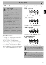
Page 33: ...5 mm five core cable on some models only 220 240 V 1N Use a 3 x 1 5 mm three core cable Power voltage Danger of electrocution Have the electrical connection performed by authorised technical personnel Use personal protective equipment The appliance must be connected to earth in compliance with electrical system safety standards Disconnect the main power supply Do not pull the cable to remove the p...

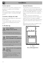
Page 34: ...ve to the installation classes Any wall units positioned above the worktop must be at a minimum distance of at least 750 mm If a hood is installed above the hob refer to the hood instruction manual to ensure the correct clearance is left Depending on the type of installation this appliance belongs to classes A Class 1 Free standing appliance Heavy appliance Danger of crush injuries Place the appli...

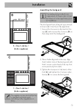
Page 35: ...t of the backguard 2 Place the backguard on the top Align the 6 bottom slots of the backguard with the 6 screws on the back of the top that were previously loosened 3 Tighten the 6 screws on the back of the hob A and tighten the 2 screws under the top B to secure the backguard The appliance must be installed by a qualified technician and according to the regulations in force The backguard provided...

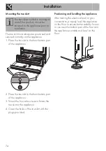
Page 36: ... to fasten the toe skirt to the appliance 4 Cover the holes of the toe skirt with the plugs provided Positioning and levelling the appliance After making the electrical and or gas connections properly level the appliance on the floor to ensure better stability Screw or unscrew the bottom part of the foot until the appliance is stable and level on the floor The toe skirt provided is an integral par...

Reviews: