background image

24

SPRAYING INTRODUCTION

This section is intended to offer practical guidelines for the distribution of liquid chemicals over an area of turf
grass such as golf courses, park land, school grounds and lawns. SMITHCO makes no representation as to
the suitability of any technique or product for any particular situation. This section is suitable for self-propelled
spray vehicles or sprayers mounted onto vehicles.

Boom Spraying is the most effective, accurate and efficient method of applying chemicals to large turf areas. It
may be done by means of:

• A dedicated spray vehicle

• A sprayer mounted upon a utility vehicle

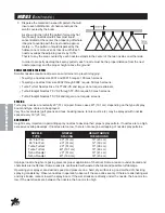
Sprayers are typically equipped with wide spray booms. Generally these booms are between 15 feet (4.5 m)
and 20 feet (6 m) in width. They are divided into three sections, with hinges that permit the long outer sections
to automatically move out of the way and reset if an obstacle such as a tree or fence is in you path.

To minimize the chance for missed areas or double application use a device to mark the outside boundaries of
each spray swath. Foam markers and dye markers are advisable.

TURF MANAGEMENT

Turf management chemicals are made for four general purposes:

1. Fungicides: Prevent or cure fungus on turf grass. They are made in 2 general types:

• Systemic - Chemicals enter the plant system and protect or cure it of, fungus.
• Contact - Kills fungus with which it comes into contact.

2. Insecticides: Eliminate damaging insects and worms (such as grubs, beetles, ants, etc.)

3. Herbicides: Control and eliminate undesirable weeds and grass from turf areas and non-turf areas such

as bunkers, trails, fences, etc.

4. Nutrients & Fertilizer: Promote growth, beauty and color in turf grass.

Some materials have to be applied so that they get into the soil below the plant leaves, This is called “soil appli-
cation”. 
In order to do this, they are best applied with a large volume of water. They are often then watered-in
using the irrigation system. This type of chemical material includes systemic chemicals and chemicals de-
signed to destroy pests which live in the thatch and the soil.

Other materials must be applied to reach a problem that is present on the plant leaves. This is called “Foliar
Application” 
and requires a lower volume of water. Instead of irrigation water, these materials are further acti-
vated by dry air and sunshine. They include contact fungicide and many herbicides.

The user of sprayers and chemicals must follow the directions provided with the spray material. It is the only
way to insure safe and effective results. It provides information on how much chemical and how much water is
to be applied to the area to be sprayed.

Though there are many types and sizes of nozzles, two specific types have proven most successful in turf
grass management.

• The first type is target-directed. It sprays material in a direct line downwards to the target turf grass.

These are flat fan nozzles, commonly referred to as TeeJet nozzles. They are available in a wide variety
of sizes for any required discharge volume rate. They are the best for many contact or foliar applied
pesticides. They are spaced either 10" (25 m) or 20" (51 cm) apart and overlap one another by about 

1

/

3

.

• The second type useful in turf management are broadcast type nozzles. They are commonly referred to

as raindrop or floodjet nozzles. They spray a hollow-cone shaped pattern of much larger droplets which
fall quickly to the turf under their own weight. They are best for systemic pesticides or any material
requiring a large volume of water for soil application. The larger droplets are not as subject to drift from
wind and are a safer, more environmentally friendly choice in many situations.

Summary of Contents for Spray star 1602HD

Page 1: ...OPERATOR S MANUAL SPRAY STAR 1600HD Model 1602HD April 2002 SMITHCO PRODUCT SUPPORT 1 800 891 9435 Hwy SS and Poplar Avenue Cameron WI 54822 E mail productsupport smithco com...

Page 2: ...Initial Console Setup 21 Console Field Test 22 Spray Operation 22 23 Spraying Procedure 24 30 Spraying Introduction 24 Turf Management 24 Hose Handgun Spraying 25 Nozzles 25 26 Calibration Introductio...

Page 3: ...nance instructions Failure to do so could result in personal injury or equipment damage Keep manuals in a safe place after operator and maintenance personnel have read them Right and left sides are fr...

Page 4: ...vel Choke Open Choke Closed Hand Throttle Hour Meter Hour Meter Fuse Glow Plug Glow Plug Off Glow Plug On RPM Gasoline Diesel Water Temperature Temperature Light Engine Oil Engine Stop Engine Start En...

Page 5: ...Parts Manual Operation Pinch Point Step Hot Surface Hydraulic Fluid Penetration Lift Arm Tractor Engage Disengage PTO Ground Speed Fast Slow H High L Low F Forward R Reverse N Neutral Warning Danger C...

Page 6: ...fore starting the engine 12 Never use your hands to search for oil leaks Hydraulic fluid under pressure can penetrate the skin and cause serious injury 13 This machine demands your attention To preven...

Page 7: ...arge line may whip 9 Periodically inspect the pump and the system components 10 Check hoses for weak or worn condition before each use Make certain that all connections are tight and secure 11 Do not...

Page 8: ...ps 575 minimum Ground Terminal Polarity Negative Maximum Length 10 25 26 cm Maximum Width 6 88 17 cm Maximum Height 10 25 cm FLUID CAPACITY Crankcase Oil 2 1 quart 2 liters with filter Fuel 5 gallon 1...

Page 9: ...ghten nut to 30 40 ft lb 41 54 Nm Do not over tighten 6 Install the seat with the stud going through the engine cover and the flat washers lock washers and nuts Use the front set of holes for shorter...

Page 10: ...ed 2 Check engine oil level Add as needed DO NOT OVERFILL 3 Tire pressure should be 20 psi 1 4 bar front and 18 psi 1 3 bar rear maximum 4 Inspect electrical system for loose connections or frayed wir...

Page 11: ...s machine is in high gear G Tilt Steering Hold lever down and adjust steering wheel to desired position H Low Speed Light When green light is on it indicates machine is in low gear K Accelerator Pedal...

Page 12: ...nob on the of the lever To tighten turn knob clockwise To loosen turn counter clockwise FOAM MARKER CONTROLS Foamer ON OFF Switch Located to the right of the control panel Used to turn on and off the...

Page 13: ...is disengaged 3 Depress the clutch pedal to activate the interlock switch 4 Place shift lever in neutral 5 The ignition switch is located to the right of the steering column In sert the key A and tur...

Page 14: ...t higher speed for transport the Ground Speed Control lever should be returned to the fast position HAND THROTTLE CONTROL LEVER Park brake must be set when engine throttle control is used To increase...

Page 15: ...f suction prime If your Spray Star is fitted with a hose reel there is a second ball valve on the discharge system to supply ma terial to the hose reel The Quadrajet agitation system operates with fou...

Page 16: ...ey is also used to select an area base measurement of US acres SI Hectares or TU 1 000 sq ft H ENTER Used only to enter the data into the Console Calibration Keys Top Row Used to enter Function Keys B...

Page 17: ...ntimeters by multiplying the number of tips times the spacing Write these boom widths down for future reference when programming the Console computer The Console is capable of controlling up to three...

Page 18: ...efine this number See definitions below Valve Backlash Controls the time of the first correction pulse after a change in correction direction is detected Incr to Decr or Decr to Incr Range 1 to 9 1 Sh...

Page 19: ...ay from US acres to SI b Depressing momentarily Steps the DATA display from SI Hectares to TU c Depressing momentarily Steps the DATA display from TU 1000 sq ft to US 2 Selecting US SI or TU a To sele...

Page 20: ...the estimated total Volume in Tank when you start spraying in key labeled Each time the tank is refilled this number must be reentered 14 Enter the TIME of day in the key labeled This is a 24 hour cl...

Page 21: ...splayed SELF TEST FEATURE SELF TEST allows speed simulation for testing the system while the vehicle is not moving Enter the simulated operating speed in the key labeled If 6 MPH 10 km h is desired en...

Page 22: ...b Enter new delay time 0 to 200 days using the same procedure as that for entering other data In the event of console power loss the power down delay time will default to 10 days CONSOLE ALARM FEATUR...

Page 23: ...NITIAL CONSOLE SETUP 1 Fill tank with water only If positive displacement type pump is used fully open pressure relief valve PRV Open gate valve between the tank and pump 2 Place MASTER On Off to On a...

Page 24: ...n soluble packs are place into the fillwell strainer basket and dissolved by adding water through the basket The balance of the water required for the spray operation is added to the tank through the...

Page 25: ...hand side of the spray tank Remove stainless steel screen Wash bowl and screen thoroughly Apply thin layer of petroleum jelly to O ring or gasket Replace screen and bowl taking care to position o rin...

Page 26: ...t into the soil below the plant leaves This is called soil appli cation In order to do this they are best applied with a large volume of water They are often then watered in using the irrigation syste...

Page 27: ...quid Obviously the larger the opening the greater the rate of flow volume Volume is expressed in Gallons Per Minute gpm or Liters Per Minute lpm Do not confuse the term volume with application rate wh...

Page 28: ...arger do not require screens SPACING Turf spray nozzles are normally 20 51 cm apart Some cases 40 101 cm depending on the type of spray boom and type of area to be sprayed Very fine level areas golf g...

Page 29: ...rent types of spray patterns of various nozzles and made our selection of type ac cordingly We now have to choose a size which will provide the correct application rate Sizes are available for all req...

Page 30: ...mph 7 10 kph The vehicle which carries or tows the sprayer should be equipped with a precise low speed speedom eter If it is not exact ground speed at a given engine speed must be determined by timin...

Page 31: ...llon Per Acre rates to Imperial Gallons per acre Imp gpa multiply by 0 83 To convert any of the Liter Per Hectare rates to Imperial Gallons Per Hectare Imp GPH multiply by 0 22 8 Checking the Actual A...

Page 32: ...te adjustments must be made 7 Minor adjustments in application rate may be made by increasing or decreasing the spraying pressure Lowering spraying pressure decreases application rate Increasing spray...

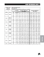
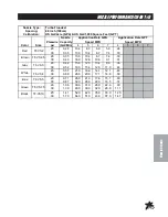
Page 33: ...0 49 21 0 26 0 30 0 36 0 16 6 21 0 24 0 29 0 13 9 17 3 19 8 24 0 11 9 14 9 17 0 21 0 0 98 1 20 1 40 1 70 0 64 0 80 0 91 1 10 0 48 0 60 0 68 0 84 0 38 0 48 0 55 0 67 Brown XR8005 DG8005 20 30 40 60 0...

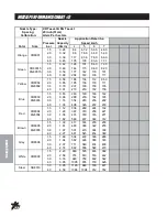
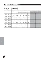
Page 34: ...236 272 142 165 202 233 Red XR8004 DG8004 1 5 2 0 3 0 4 0 1 12 1 29 1 58 1 82 336 387 474 546 269 310 379 437 224 258 316 364 192 221 271 312 Brown XR8005 DG8005 1 5 2 0 3 0 4 0 1 39 1 61 1 97 2 27 41...

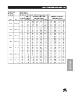
Page 35: ...69 21 0 26 0 16 9 20 0 14 1 17 1 12 1 14 6 48 59 Blue TF VS5 20 30 0 71 0 87 26 0 32 0 21 0 26 0 17 6 22 0 15 1 18 5 60 74 Green TF VS7 5 20 30 1 06 1 30 39 0 48 0 31 0 39 0 26 0 32 0 22 0 28 0 90 1...

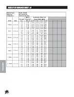
Page 36: ...White TF VS4 1 5 2 0 2 23 2 57 335 386 223 257 167 193 112 129 Blue TF VS5 1 5 2 0 2 79 3 22 419 483 279 322 209 242 167 193 Green TF VS7 5 1 5 2 0 4 19 4 83 629 726 419 484 314 363 251 290 Black TF...

Page 37: ...9 45 50 28 31 36 40 23 26 30 33 1 1 1 2 1 4 1 5 80 88 1 0 1 1 64 71 82 91 53 59 68 76 White 1 4 TTJ08 VS 25 30 40 50 63 69 80 89 62 68 79 88 47 41 59 66 37 41 48 53 31 34 40 44 1 4 1 6 1 8 2 0 1 1 1 2...

Page 38: ...18 Gray 1 4 TTJ06 VS 1 0 1 5 2 0 3 0 1 37 1 68 1 94 2 37 206 252 291 356 137 168 194 237 103 126 146 178 82 2 101 116 142 White 1 4 TTJ08 VS 1 0 1 5 2 0 3 0 1 82 2 23 2 57 3 15 273 335 385 473 182 223...

Page 39: ...ME 1 US Gallon x 128 Fluid Ounces 1 US Gallon x 3 785 Liters 1 US Gallon x 0 83267 Imperial Gallons 1 US Gallon x 8 34 Pounds Water 1 Gallon Per Acre 2 9 Fluid Ounces per 1 000 Square Feet 9 35 Liters...

Page 40: ...requirements of the Directive 89 392 EEC if applicable and to the requirements of the other Directives EN292 1 339 93 EEC EN292 2 91 368 EEC EN294 2000 14 EC EN349 98 37 Title and or number and date...

Page 41: ...t covered under this warranty nor is any loss of income and or other loss resulting from the failure of the product to function due to a warranty defect The following items are not covered under the S...

Page 42: ...Part 74 17 041503...
Reviews: