background image

NÉCESSAIRES, PIÈCES ET ACCESSOIRES (SUITE)

3A

182485 POIGNÉE, POMPE

3B

182711 BAGUE DE BLOCAGE DE LA 

POIGNÉE

3C

182704 RESSORT (2)

3D

182484 PINCE 4 DOIGTS

3E

182714 TANK COVER

3F

182712 RONDELLE PLATE

3G

182713 ANNEAU DE RETENUE

3H

182519 JOINT TORIQUE 105 mm x 

5,7 mm, V

3J

182715 TIGE DE POMPE

3K

182706 ASSISE DE SOUPAPE

3L

182523 JOINT TORIQUE 30 mm x 4 mm, V

3M

182707 PLAQUE À PISTON

3N

182708 CONTRE-ÉCROU

3P

182524 JOINT TORIQUE 46 mm x 3,5 mm, 

V

3R

182710 CORPS DE POMPE

3S

182535 CLAPET ANTI-RETOUR, POMPE, V

KIT N° 3   182522  POMPE Viton

 (Joints toriques et joint marron)

N° DE 

CLE

N° DE 

PIÈCE

DESCRIPTION

5

182677 CEINTURE-BAUDRIER

6

182567 BUSE, RÉGLABLE, LAITON


7

-1

182578 EMBOUT JET PINCEAU, LAITON, 0,2 GPM-65°

-2

176042 EMBOUT JET PINCEAU, LAITON, 0,2 GPM-80°

-3

176116 EMBOUT JET PINCEAU, LAITON, 0,4 GPM-80°

-4

176171 EMBOUT JET PINCEAU, LAITON, 0,5 GPM-80°

-5

182577 EMBOUT JET PINCEAU, LAITON, 0,5 GPM-95°

-6

182576 EMBOUT JET PINCEAU, LAITON, 0,1 

GPM-110°


8

-1

182795 BUSE No 4, POLY VERTE, 0,07 GPM-80°

-2

182796 BUSE No 6 POLY ROUGE, 0,10 GPM-80°

-3

182797 BUSE No 10 POLY NOIRE, 0,10 GPM-80°

-4

182784 BUSE No 8 POLY GRISE, 0,13 GPM-80°

-5

182798 BUSE No 12 POLY MARRON, 0,20 GPM-80°

-6

182785 BUSE No 8 LAITON À JET CONIQUE

9

183300 SOUPAPE DE FERMETURE

A

182519 JOINT TORIQUE 105 mm x 5,7 mm, 

VITON

B

182535 CLAPET ANTI-RETOUR, POMPE 

VITON

C

182523 JOINT TORIQUE 30 mm x 4 mm, 

VITON

D

182524 JOINT TORIQUE 46 mm x 3,5 mm, 

VITON

KIT N° 4   182644    JOINTS DE POMPE VITON

(Joints toriques et joint marron)

KIT N° 10  183525  NÉCESSAIRE D’ENTRETIEN

DE SOUPAPE DE FERMETURE

10A

182474 JOINT TORIQUE, 1,9mm x 4,2mm, VITON

10B

183304 TIGE DE SOUPAPE, LAITON

10C

182476 JOINT DE SOUPAPE, VITON

10D

183305 BASE DE SOUPAPE, LAITON

10E

183306 RESSORT, SOUPAPE

10F

183303 BOUCHON, SOUPAPE

10G

182468 JOINT TORIQUE, 2,4mm x 11,2mm, VITON

10H

182467 FILTRE

N° DE 

CLE

N° DE 

PIÈCE

DESCRIPTION

1

182521 RÉSERVOIR DE 3,5 GALLONS, 

VITON (INCLUT LA LÉGENDE N°2)

 2

182678 ENSEMBLE SOUPAPE DE 

DÉCHARGE VITON 

KEY#

PART# DESCRIPTION

11

-1

183294 ENSEMBLE LANCE DE 24 po, LAITON

-2

183296 ÉCROU, BOUCHON EN LAITON

12

183381 ENSEMBLE FLEXIBLE

Page 28

LES NÉCESSAIRES D’ENTRETIEN, LES PIÈCES ET LES ACCESSOIRES SONT DISPONIBLES EN 

CONTACTANT

The Fountainhead Group, Inc. - Customer Service Center

par téléphone du lundi au vendredi, de 8 h à 17 h HNE

au numéro sans frais : +1-800-311-9903

ou

par courriel : Info@TheFGI.com

ou

par accès en ligne sur : www.TheFountainheadGroup.com

                                      www.smithperformancesprayers.com

Summary of Contents for 190448

Page 1: ...ation or Parts Call 1 800 311 9903 The Fountainhead Group Inc 23 Garden St New York Mills NY 13417 1 800 311 9903 www TheFountainheadGroup com www smithperformancesprayers com CAUTION Read and follow...

Page 2: ...ppropriate technical bulletin for the chemical being sprayed for additional protective clothing required Read and follow all instructions and cautions on label material safety data sheets and technica...

Page 3: ...e C 3 Install selected nozzle into the extension nut and tighten nut securely using a 13 16 wrench See Figure C 80 FAN 07 GPM 4 GREEN 80 80 80 80 SPRAY ANGLE SPRAY PATTERN FAN FAN FAN FAN FLOW RATE 10...

Page 4: ...l spring and turn handle 1 4 turn counterclockwise to unlock handle Pressurize the sprayer by pumping the handle in a smooth up and down motion Push down on the handle to depress coil spring and turn...

Page 5: ...reservoir then release pressure and remove the pump from the tank 6 Tip and empty tank then set tank upright Hold wand and shut off above the tank and depress the shut off The liquid will drain into t...

Page 6: ...l and unscrew by turning counterclockwise as shown See Figure F A strap wrench may be required to loosen barrel 3 Inspect barrel o ring If worn or damaged remove and replace Lubricate o ring with petr...

Page 7: ...ring 3L 2 Piston o ring 3L is dry 1 Replace piston o ring as described in Pump Disassembly Reassembly section 2 Lubricate piston o ring as described in Pump Disassembly Reassembly section Sprayer tan...

Page 8: ...S KIT 3 1 2 3A 3B 3D 3C 3E 3F 3G 3H 3J 3K 3L 3M 3N 3P 3R 3S 3C 6 8 1 8 2 8 3 8 4 8 5 7 1 7 2 7 3 7 4 7 5 7 6 8 6 10G 10F 10B KIT 10 D A C B KIT 4 5 11 1 11 2 12 SHUT OFF 9 10A 10B 10H 10G 10D 10C 10E...

Page 9: ...E 10 BLACK POLY 10 GPM 80 4 182784 NOZZLE 8 GRAY POLY 13 GPM 80 5 182798 NOZZLE 12 BROWN POLY 20 GPM 80 6 182785 NOZZLE 8 BRASS CONICAL 9 183300 SHUT OFF A 182519 O RING 105mm x 5 7mm VITON B 182535 C...

Page 10: ...arden St New York Mills NY 13417 1 800 311 9903 www TheFountainheadGroup com www smithperformancesprayers com PRECAUCI N Lea y siga todas las instrucciones Serie industrial y para contratista S103E 19...

Page 11: ...a el producto qu mico a ser rociado Lea y siga todas las instrucciones y precauciones de las etiquetas de las hojas de datos de seguridad y de los boletines t cnicos de los productos utilizados en est...

Page 12: ...ale la boquilla seleccionada en la tuerca de la extensi n y apriete la tuerca firmemente con una llave de 13 16 Vea la figura C USOS DE BOQUILLAS DE ABANICO AJUSTABLE DE BRONCE Utilizadas en 1 Serie p...

Page 13: ...un movimiento suave ascendente y descendente Empuje el asa hacia abajo para presionar el resorte helicoidal y gire el asa 1 4 de vuelta hacia la derecha y luego deje que el asa se eleve hasta su posic...

Page 14: ...tanque y a continuaci n p ngalo en posici n vertical Sostenga la extensi n y el dispositivo de cierre por encima del tanque y presione el dispositivo de cierre El l quido drenar dentro del tanque vuel...

Page 15: ...zquierda como se muestra Vea la figura F Podr a ser necesario una llave de correa para aflojar el cilindro 3 Inspeccione la junta t rica del cilindro Si est desgastada o da ada qu tela y reempl cela L...

Page 16: ...n la bomba 2 V lvula de retenci n de la bomba 3S astillada rasgada o dilatada 1 Limpie la v lvula de retenci n 3S y la superficie sellada de la v lvula en la bomba 2 Reemplace la v lvula de retenci n...

Page 17: ...3 1 2 3A 3B 3D 3C 3E 3F 3G 3H 3J 3K 3L 3M 3N 3P 3R 3S 3C 6 8 1 8 2 8 3 8 4 8 5 7 1 7 2 7 3 7 4 7 5 7 6 8 6 D A C B JUEGO 4 5 11 1 11 2 12 P gina 17 10G 10F 10B JUEGO 10 CIERRE 9 10A 10B 10H 10G 10D 10...

Page 18: ...O 110 8 1 182795 BOQUILLA 4 VERDE DE POLICARBONATO 07 GALONES POR MINUTO 80 2 182796 BOQUILLA 6 ROJA DE POLICARBONATO 10 GALONES POR MINUTO 80 3 182797 BOQUILLA 10 NEGRA DE POLICARBONATO 10 GALONES PO...

Page 19: ...ONIBLES CONTACTANDO A The Fountainhead Group Inc Centro de Servicio al Cliente Lunes a viernes de 8 am a 5 pm hora del este N mero gratuito 1 800 311 9903 o al correo electr nico Info TheFGI com o al...

Page 20: ...en St New York Mills NY 13417 1 800 311 9903 www TheFountainheadGroup com www smithperformancesprayers com Notice d utilisation et d entretien S rie Industrie et entreprises du b timent S103E 190448 P...

Page 21: ...tin technique du produit utilis pour savoir quels v tements de protection porter Lire et suivre le mode d emploi et les mises en garde figurant sur l tiquette sur les fiches signal tiques sant s curit...

Page 22: ...13 16 po Voir la figure C 3 Placer la buse s lectionn e dans l crou de la rallonge et bien serrer l crou l aide d une cl de 13 16 po Voir la figure C 80 FAN 07 GPM 4 VERTE 80 80 80 80 SPRAY ANGLE SPR...

Page 23: ...mouvement r gulier pour mettre le pulv risateur sous pression Appuyer sur la poign e pour enfoncer le ressort h lico dal la tourner d 1 4 de tour dans le sens des aiguilles d une montre puis la laisse...

Page 24: ...t de le redresser Tenir la lance et la soupape de fermeture au dessus du r servoir et appuyer sur la soupape de fermeture pour que le liquide s coule dans le r servoir et le vider nouveau 7 Recommence...

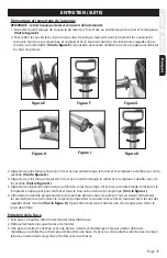
Page 25: ...guilles d une montre comme illustr Voir la figure F Il peut tre n cessaire d utiliser une cl sangle pour d visser le corps de pompe 3 Inspecter le joint torique du corps S il est us ou endommag le ret...

Page 26: ...emplacer le joint torique du piston comme d crit dans la section D montage et remontage de la pompe 2 Lubrifier le joint torique du piston comme d crit dans la section D montage et remontage de la pom...

Page 27: ...2 3A 3B 3D 3C 3E 3F 3G 3H 3J 3K 3L 3M 3N 3P 3R 3S 3C 6 8 1 8 2 8 3 8 4 8 5 7 1 7 2 7 3 7 4 7 5 7 6 8 6 D A C B KIT N 4 5 11 1 11 2 12 Page 27 10G 10F 10B KIT N 10 SOUPAPE DE FERMETURE 9 10A 10B 10H 1...

Page 28: ...80 5 182798 BUSE No 12 POLY MARRON 0 20 GPM 80 6 182785 BUSE No 8 LAITON JET CONIQUE 9 183300 SOUPAPE DE FERMETURE A 182519 JOINT TORIQUE 105 mm x 5 7 mm VITON B 182535 CLAPET ANTI RETOUR POMPE VITON...

Reviews: