65
Accessories
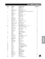
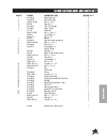
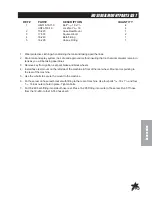
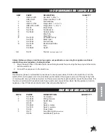
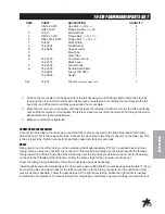
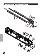
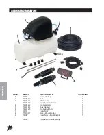
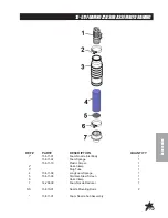
10-378 FOAM MARKER FOR 1000 PARTS LIST
REF#
PART#
DESCRIPTION
QUANTITY
1
HB-14-20-075
Hex Bolt,
1
/
4
-20 x
3
/
4
4
HNFL-14-20
Flange Lock Nut,
1
/
4
-20
4
2
10-413
Foamer Brace
1
3
HB-12-13-150
Flange Bolt,
5
/
16
-18 x 1
1
/
2
1
4
HBFL-516-18-075
Flange Bolt,
5
/
16
-18 x
3
/
4
2
5
10-409
Mount Plate
1
A
14-291-04
Tank Bracket
2
B
14-284-02
Cap Assembly
1
C
Blue Tube
1
D
Clear Tube
1
E
14-291-03
Compressor Only
1
14-291-01
Black Cover
1
F
14-291-02
Foamer Tank
1
G
14-291-05
Double Switch Box
1
33-508
Fuse
1
15-506-02
Switch
1
A-G
14-291
Foamer
(includes parts A-G)
1
Safety: Before working on machine stop engine, set park brake, remove key from ignition and block
wheels. Disconnect negative (-) battery terminal.
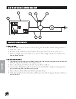
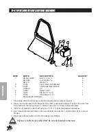
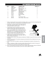
1. Mount the switch box on the side control panel facing towards the seat using the two wing nuts that came
with the switch box.
2. Connect the compressor to the switch box.
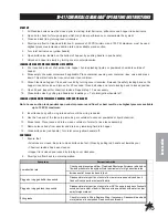
WIRING
Use dielectric grease on all electrical connections. Connect power cable (15-509) to the switch box. Turn the
switch off. Route the power wire to the fuse block (on the inside of the engine cover) out of the way of any heat
or moving parts. Use nylon ties as needed. Cut the power wire with enough length to connect the fuse block. Put
the slide on terminal with heat shrink onto the wire ends and connect to fuse block. Red to po), black to
negative(-). Insert 10 amp fuse into slot which has red wire attached to it.
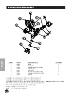
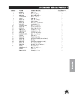
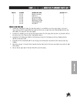
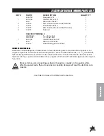
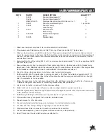
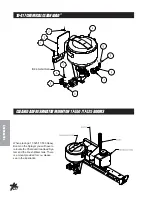
FOAM MARKER WIRING PARTS LIST
REF#
PART#
DESCRIPTION
QUANTITY
1
14-291-03
Compressor
1
2
15-504-04
Wiring Harness
1
3
14-291-05
Switch Box
1
33-508
Fuse
1
15-506-02
Switch - Center
1
14-291-14
Switch - outside
1
4
15-509
Power Cable
1
5
33-271
Fuse Block (part
of machine)
1
33-508
Auto Blade Type Fuse
1
Summary of Contents for 10-100-C
Page 10: ...8 Service END USER S SERVICE CHART Duplicate this page for routine use...
Page 13: ...NOTES...
Page 14: ...12 Diagrams WIRING DIAGRAM...
Page 16: ...14 Diagrams HYDRAULIC DIAGRAM...
Page 18: ...16 Parts BODY FRAME DRAWING...
Page 20: ...18 Parts NOSECONEDRAWING...
Page 22: ...20 Parts FRONTAXLEDRAWING...
Page 24: ...22 Parts SEATCONSOLEANDROPSDRAWING...
Page 26: ...24 Parts FUELTANKDRAWING...
Page 28: ...26 Parts OILTANK OILFILTER OILCOOLERDRAWING...
Page 30: ...28 Parts FOOTPEDALLINKAGE DRAWING...
Page 32: ...30 Parts ENGINE PUMPSANDEXHAUSTDRAWING...
Page 34: ...32 Parts PARKBRAKEANDREARAXLEDRAWING...
Page 36: ...34 Parts TANKDRAWING TURBO QUADAGITATORDRAWING...
Page 38: ...36 Parts 15 301ORBITROLDRAWING...
Page 40: ...38 Parts 10 117 HYDRAULIC PUMP DRAWING...
Page 42: ...40 Parts 16 998HYPROPUMPDRAWING...
Page 44: ...42 Parts 10 116WHEELMOTOR 14 0 CI DRAWING...
Page 50: ...48 Accessories 16 524 MOTORIZEDCONTROLVALVEDRAWING 15 737STRAINER...
Page 52: ...50 Accessories 17 575 SMITHCOSUPERBOOM...
Page 56: ...54 Accessories 16 906ELECTRICHOSEREELDRAWING...
Page 58: ...56 Accessories 16 129MANUALHOSEREELDRAWING...
Page 60: ...58 Accessories 10 422HOSEREELMOUNT FOR17 525 17 550BOOMS...
Page 62: ...60 Accessories 1008 RAVEN 440 HOSE REEL PLUMBING DRAWING...
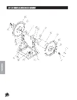
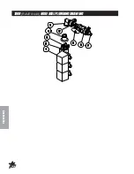
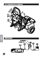
Page 66: ...64 Accessories 10 378FOAMMARKERFOR1000DRAWING WIRINGDRAWING...
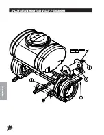
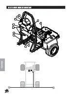
Page 68: ...66 Accessories 10 378FOAMMARKER DRAWING...
Page 70: ...68 Accessories FOAMER NOZZLEMOUNT HOSEGUARDMOUNTDRAWING...
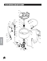
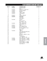
Page 78: ...76 Accessories 15 620CHEMICALCLEANLOAD DRAWING...

