background image

86

Accessories

When placing a 17-525/17-550 Heavy 

Boom on the Sprayer you will have 

to relocate the Chemical Clean-load 

System and the Fresh Water tank. 

There is a mount provided for you, 

please see in the illustration.

10-417 CHEMICAL CLEAN-LOAD 

®

CLEAN LOAD FRESHWATER MOUNT ON 17-550/17-525 BOOMS

Summary of Contents for 10-100-D

Page 1: ...Spray Star 1008J 10 100 D with TeeJet Radion 8140 SN 100631 February 2018 Product Support Hwy SS Poplar Ave Cameron WI 54822 1 800 891 9435 productsupport smithco com Parts Service ...

Page 2: ... 576 Orbitrol 40 41 42 797 Hydraulic Pump 42 43 16 998 Hypro Pump 44 10 510 Wheel Motor 45 Accessories 46 90 1008 Plumbing 46 47 1008 Wiring 48 15 743 Manifold Ball Valve 49 20 685 Regulator Valve 50 14 801 Agitation Strainer 51 17 737 Strainer 52 Nozzles 53 17 835 15 17Nozzle Heavy Duty Boom 54 64 Triple Nozzle Assembly 65 66 10 370 Water Fill Meter Kit 67 16 906 Electric Hose Reel 68 69 16 129 H...

Page 3: ...ailure to do so could result in personal injury or equipment damage Keep manuals in a safe place after operator and maintenance personnel have read them Right and left sides are from the operator s seat facing forward All Smithco machines have a Serial Number and Model Number Both numbers are needed when ordering parts The serial number plate on the Spray Star 1000 is located on the left side in f...

Page 4: ...rake before starting the engine 12 Never use your hands to search for oil leaks Hydraulic fluid under pressure can penetrate the skin and cause serious injury 13 This machine demands your attention To prevent loss of control or tipping of the vehicle A Use extra caution in backing up the vehicle Ensure area is clear B Do not stop or start suddenly on any slope C Reduce speed on slopes and in sharp...

Page 5: ...d 0 8 mph 0 12 8 kph Reverse Speed 0 3 mph 0 4 8 kph BATTERY Automotive type 24F 12 Volt BCI Group Size 24 Cold Cranking Amps 575 minimum Ground Terminal Polarity Negative Maximum Length 10 25 26 cm Maximum Width 6 88 17 cm Maximum Height 10 25 cm FLUID CAPACITY Crankcase Oil See Engine Manual Fuel 6 gallon 22 7 liters Hydraulic Fluid 5 gallon 19 liters Grade of Hydraulic Fluid SAE 10W 40 API Serv...

Page 6: ...er first 5 hours and every 200 hours thereafter 7 Lower machine to ground and remove blocks and jack TIRE PRESSURE Caution must be used when inflating a low tire to recommended pressure Over inflating can cause tires to explode All tires should be 20 psi 1 4bar Improper inflation will reduce tire life considerably LUBRICATION Use No 2 General purpose lithium base grease and lubricate every 100 hou...

Page 7: ...le engine bore damage due to inadequate lubrication HYDRAULIC OIL 1 Use SAE 10W 40 API Service SJ or higher motor oil 2 For proper warranty change oil every 500 hours or annually which ever is first 3 Oil level should be 2 2 5 6 4cm from top of the tank when fluid is cold Do not overfill 4 After changing oil run the machine for a few minutes Check oil level and for leaks 5 Always use extreme cauti...

Page 8: ...eed the recommended charging rate If electrolyte starts boiling over decrease charging Always remove grounded battery clamp first and replace it last Avoid hazards by 1 Filling batteries in well ventilated areas 2 Wear eye protection and rubber gloves 3 Avoid breathing fumes when electrolyte is added 4 Avoid spilling or dripping electrolyte Battery Electrolyte is an acidic solution and should be h...

Page 9: ...ses and fittings Inspect and clean the machine After the first 50 hours Change Hydraulic Oil Filter Every 100 hours Clean or change air filter 1 Clean pre cleaner 1 Change engine oil and filter Replace spark plug Lubricate machine Clean or change remote air cleaner Check the battery fluid level and cable connections Check muffler and spark arrestor Check belt tension Every 250 hours Check engine v...

Page 10: ...ean the air filter Clean the engine cooling fins Check for unusual engine noises Check the hydraulic oil level Check hydraulic hoses and fittings for damage Check for fluid leaks Check the tire pressure Check the Instrumentation Inspect electrical system for frayed wires Check park brake adjustment Change oil filter Change oil Lubricate Machine Ensure all warning decals are intact Areas of Concern...

Page 11: ...se decreases speed Disengage the lever and you will have full accel erator pedal range FLOW METER MAINTENANCE AND ADJUSTMENT 440 SYSTEM ONLY 1 Remove Flow meter from Sprayer brush away any debris and flush with clean water to remove any foreign material 2 Remove the retaining rings carefully Remove the bearing hub turbine hub and turbine from inside flow meter 3 Clean the turbine and hubs of metal...

Page 12: ...lizer follow manufacturers recommendations and add the correct amount for the capacity of fuel system Fill fuel tank with clean fresh gasoline Run engine for 2 3 minutes to get stabilized fuel into carburetor Close fuel shut off valve when unit is being stored or transported To empty the system drain fuel tank and carburetor or run engine until tank and system are empty 4 Remove the spark plugs Ad...

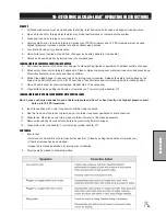
Page 13: ...11 NOTES ...

Page 14: ...12 Diagrams WIRING DIAGRAM ...

Page 15: ...tary On Off On 1 9 30 214 KYB Electric Hydraulic Actuators 2 10 16 998 Hypro Pump With Electric Clutch 1 11 33 480 Pressure Switch 1 12 77 207 Buzzer 1 8875 Male Bullet 2 8963 Heat Shrink 2 13 10 575 Briggs 23HP Engine 1 14 22 017 Starter Cable 1 15 13 750 Solenoid w Connector 1 16 22 055 Red Battery Cable 1 17 33 216 Battery 1 18 76 327 Ground Battery Cable 1 19 77 261 Circuit Breaker 1 8977 Circ...

Page 16: ...14 Diagrams HYDRAULIC DIAGRAM ...

Page 17: ...embly 4 11 10 584 Hydraulic Hose x 23 1 12 18 302 Union Tee 1 2 13 10 571 Hydraulic Hose x 21 5 1 14 42 797 Variable Pump 1 15 8832 29 3 4 Suction Hose x 29 1 18 040 Hose Clamp 2 16 34 123 Elbow 3 17 23 006 Oil Filter 1 23 031 Filter Element 25 Micron 1 18 10 570 Hydraulic Hose x 47 1 19 60 473 Oil Tank 1 20 60 213 Strainer 1 21 10 566 STC Hydraulic Hose x 85 1 22 8832 16 3 4 Suction Hose x 16 1 1...

Page 18: ...16 Parts BODY FRAME DRAWING ...

Page 19: ...14 17 524 Oval Head Lights 2 15 15 822 Nose Cone 1 16 10 630 Mainframe 1 17 10 385 Front Panel 1 18 10 479 Seat Panel 1 19 80 020 Choke 1 20 45 118 Throttle Control with Cable 1 21 60 106 Park Brake Handle 1 22 10 631 Right Front Fender 1 23 16 857 Tire and Wheel 2 16 857 01 Tire 20 x 10 10NHS 4 Ply 2 42 161 02 Wheel 2 24 10 595 RH Control Panel 1 25 27 055 Seat Hinge 4 26 10 438 Right Side Panel ...

Page 20: ...18 Parts NOSE CONE DRAWING ...

Page 21: ...x 1 7 HNFL 516 18 Flange Loc Nut 5 16 18 7 17 10 164 Reverse Pedal 1 18 HSTP 516 18 075 Machine Screw 5 16 18 x 3 4 4 HNFL 516 18 Flange Lock Nut 5 16 18 4 19 10 599 Main Frame 1 20 48 132 Short Pedal Pad 1 21 48 066 Pedal Pad 1 22 10 163 Forward Foot Pedal 1 23 10 459 Hose Guard 1 24 10 458 Spray Switch Plate 440 System 1008 1 25 33 509 Master Boom Switch 440 System 1008 1 HBM 6 1 16 Metric Bolt ...

Page 22: ...20 Parts FRONT AXLE DRAWING ...

Page 23: ...5 8 13 4 1 HP 18 100 Cotter Pin 1 8 x 1 1 13 18 188 45 Elbow 1 14 77 263 Hydraulic Cylinder 1 14 530 Seal Kit 1 15 18 168 90 Elbow 1 16 HNJ 58 18 Jam Nut 5 8 18 3 17 HB 58 11 250 Bolt 5 8 11 x 21 2 3 18 18 154 Rod End 3 HG 14 28 180 Grease Fitting 1 4 28 x 180 3 19 HMB 58 14 Machine Bushing 5 8 x 14GA 6 20 HNL 12 20 Lug Nut 1 2 20 10 21 27 022 02 Stud 1 2 20 10 22 10 582 Spindle 2 18 035 Bushing p...

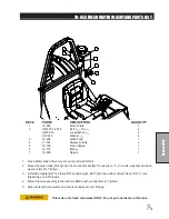
Page 24: ...22 Parts SEAT CONSOLE AND ROPS DRAWING ...

Page 25: ... 081 Rubber Bumper 2 HNTL 38 16 Lock Nut 3 8 16 2 12 HW 38 Washer 3 8 2 HP 18 075 Cotter Pin 1 8 x 3 4 2 13 15 786 Hood Rod 1 14 10 479 Seat Panel 1 15 14 294 Seat Kit 1 14 270 Seat 14 292 Seat Switch 16 10 438 LH Rear Seat Panel 1 17 13 747 Filler Breather 1 60 473 Oil Tank 1 18 10 120 Speed Boss Handle 1 19 10 632 LH Front Fender 1 20 15 781 Cup Holder 1 21 10 596 LH Control Panel 1 22 10 385 Fr...

Page 26: ...24 Parts FUEL TANK DRAWING ...

Page 27: ... 2 9 HB 12 13 150 Bolt 1 2 13 x 11 2 4 HNTL 12 13 Lock Nut 1 2 13 4 10 8 688 Carbon Canister Mount 1 11 8 693 Hose Connector comes with engine 1 12 8 689 Carbon Canister 1 13 10 575 Engine B S 23HP 1 14 50 403 In line Gas Filter replacement 18 186 Hose Clamp 1 15 9025 28 3 16 Fuel Hose x 28 1 18 186 Hose Clamp 2 16 10 580 Engine Plate 1 17 8800 46 1 4 Fuel Hose 46 1 18 186 Hose Clamp 2 18 HB 14 20...

Page 28: ...26 Parts OIL TANK OIL FILTER OIL COOLER DRAWING ...

Page 29: ...old down 1 HB 516 18 150 Bolt 5 16 18 x 11 2 1 HW 516 Washer 5 16 1 HNTL 516 18 Lock Nut 5 16 18 1 12 60 213 Strainer 1 13 34 123 Elbow 3 14 8832 29 3 4 Suction Hose x 29 1 18 040 Hose Clamp 2 15 10 572 Hydraulic Hose 24 1 16 10 592 Cooler Mount 1 17 34 105 Oil Cooler 1 18 HB 516 18 100 Bolt 5 16 18 x 1 4 HNFL 516 18 Flange Loc Nut 5 16 18 4 19 HB 14 20 075 Bolt 1 4 20 x 3 4 2 HW 14 Washer 1 4 2 H...

Page 30: ...28 Parts FOOT PEDAL LINKAGE DRAWING ...

Page 31: ... Grease Fitting 1 4 28 x 180 part of 76 296 2 11 HP 18 100 Cotter Pin 1 8 x 1 2 12 48 132 Short Pedal Pad 1 13 10 164 Reverse Foot Pedal 1 14 HN 516 24 Nut 5 16 24 6 15 10 597 Short Connector Link 1 HN 516 24 Nut 5 16 24 2 16 10 579 Control Relay 1 17 18 234 Bushing part of 10 579 2 18 HP 18 100 Cotter Pin 1 8 x 1 1 19 10 565 Cable 1 20 HG 14 28 180 Grease Fitting 1 4 28 x 180 1 21 10 598 Long Con...

Page 32: ...30 Parts PUMP DRAWING ...

Page 33: ...Plug 1 16 23 130 Elbow 1 17 18 133 Barb Fitting 1 2 MPT X 3 4 HB 1 18 18 188 45 Elbow 1 19 HSSH 12 13 175 Socket Screw 1 2 13 x 13 4 2 HNFL 12 13 Flange Loc Nut 1 2 13 2 20 42 246 Hub 3 4 1 21 42 361 Tensioner Spacer 1 22 42 331 Pulley 2 23 42 358 Idler Pulley 1 24 42 338 Oilite Bushing 1 25 42 327 Belt Tensioner 1 26 16 990 Spacer 1 27 HB 38 16 275 Bolt 3 8 16 x 23 4 1 HW 38 Washer 3 8 1 HNTL 38 ...

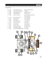
Page 34: ...32 Parts ENGINE DRAWING ...

Page 35: ...4 16 880 Close Nipple 11 4 1 15 18 390 Pipe Tee 11 4 1 16 16 156 Elbow 11 4 MPT x 11 4 HB 2 17 10 389 Plug 11 4 1 18 33 480 Pressure Switch 1 19 16 825 Hex Bushing 11 2 x 11 4 1 20 16 161 Fitting 11 4 MPT x 11 4 HB 2 21 33 494 Male Elbow 1 22 10 593 Hypro Pump Mount 1 23 HB 38 16 175 Bolt 3 8 16 x 13 4 2 HW 38 Washer 3 8 2 HTNL 38 16 Lock Nut 3 8 16 24 HB 516 18 175 Bolt 5 16 18 x 3 4 2 HW 516 Was...

Page 36: ...34 Parts PARK BRAKE DRAWING ...

Page 37: ...Short Elbow 4 14 HCP 516 100 Clevis Pin 5 16 x 1 2 HP 18 100 Cotter Pin 1 8 x 1 2 15 Carrier Side Pad 1 16 Carrier Side Pad Support 1 17 Cam Side Pad Support 1 18 Cam Side Pad 1 19 76 241 Right Caliper CW 1 20 14 265 Nut 1 20 included with Ref 24 2 21 60 268 Lug Bolt 1 2 20 x 15 16 10 22 76 239 8 Brake Disk 5 hole 2 23 HNFL 12 13 Flange Loc Nut 1 2 13 8 24 10 510 Wheel Motor 2 25 HB 12 13 750 Bolt...

Page 38: ...36 Parts REAR AXLE DRAWING ...

Page 39: ...16 18 Flange Loc Nut 5 16 18 8 7 78 221 Rear Tire and Wheel 2 78 221 01 Tire 2 78 221 02 Wheel 2 8 16 557 Square Cap 2 9 17 615 Boom Carrier 2 10 17 614 Boom Spacer 2 11 HB 516 18 100 Bolt 5 16 18 x 1 12 HW 516 Washer 5 16 12 HNFL 516 18 Flange Loc Nut 5 16 18 12 12 20 555 U bolt 4 HNFL 12 13 Flange Loc Nut 1 2 13 8 13 HB 12 13 125 Bolt 1 2 13 x 11 4 4 HN 12 13 Nut 1 2 13 4 14 HB 516 18 125 Bolt 5...

Page 40: ...38 Parts TANK DRAWING TURBO QUAD AGITATOR DRAWING ...

Page 41: ...16 100 Bolt 3 8 16 x 1 1 HNTL 38 16 Lock Nut 3 8 16 2 13 16 150 Double Threaded Fitting 3 4 2 14 10 112 Tank Carrier 1 15 16 155 Elbow 3 4 MPT x 1 HB 1 16 16 156 Elbow 11 4 MPT x 11 4 HB 1 17 16 194 Anti Vortex Fitting 11 4 1 18 16 998 Hypro Pump 1 19 33 494 Male Elbow 2 20 8954 30 Clear Hose 3 16 ID 1 18 116 Hose Clamp 2 21 10 390 Reducer 1 22 10 639 Lid Stop 1 HRS 316 100 Rivet 3 16 x 1 2 HW 316...

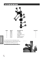
Page 42: ...40 Parts 10 576 ORBITROL DRAWING ...

Page 43: ...in 1 15 Spool 1 16 Spring Retaining Ring 1 17 10 576 05 Gerotor 1 18 O Ring 1 19 Seal Ring 1 20 15 301 03 End Cap 1 21 10 576 06 Cap Screw 7 15 301 01 Seal Kit 1 15 301 15 Centering Spring Kit 1 10 576 ORBITOR SPECIFICATIONS Inlet Relief Valve Setting 1020 psi 70 bar Nominal Flow 3 gpm 11 lpm Displacement 4 50 cu in R 73 8 cu cm R Check Valve for Manual Steering Yes Inlet Pressure Rating 2030 psi ...

Page 44: ...ng 1 4 42 003 16 Cylinder block kit 1 4A Piston assembly 9 4B Slipper retainer 1 4C Cylinder block 1 6 Swash Plate 1 7 14 114 Thrust plate 1 9 Charge pump housing assembly 1 10 42 003 10 Ball bearing 1 12 Shaft 1 14 O ring 1 15 14 217 Roller bearing 1 16 Plug 1 16A O ring 1 17 14 212 Trunnion shaft 1 18 42 003 11 Screw 4 ...

Page 45: ... 1 39 10 117 03 Plug 2 42 O ring 2 43 34 109 01 Valve plate 1 44 42 003 08 Gerotor assembly 1 46 14 107 Gasket 1 47 14 215 Pin 1 49 34 109 02 Charge relief cone 1 50 42 003 07 Needle bearing 1 53 42 159 05 Plug 1 53A O ring 1 54 14 132 Retaining ring 1 55 42 003 09 Retaining ring 1 60 34 109 02 Poppet 1 69 Spring 2 70 O ring 2 73 O ring 1 76 34 109 03 Shim kit 1 97 42 003 03 Plug assembly 2 97A O ...

Page 46: ...998 06 Mounting Flange 1 10 16 998 07 Bolt 11 16 966 06 Slinger Ring 1 12 16 966 10 Ball Bearing 2 13 16 966 12 Pump Shaft 1 14 16 822 20 Key 1 15 16 966 13 Bearing Retainer 1 16 16 994 05 Bolt 1 17 16 994 06 Retaining Washer 1 18 16 994 03 Spacer 1 19 Bolt 4 20 16 994 01 Clutch 1 21 16 994 04 Set Screw 3 16 998 12 Pump Only 16 967 Silicone Carbon Seal Kit When servicing the spray pump or filter a...

Page 47: ...aring 1 7 10 510 01 Drive Link 1 8 Ring Seal 5 9 13 032 31 Manifold 1 10 13 032 32 Commulator Assembly matched set 1 11 13 032 33 End Cover 1 12 10 510 02 Special Bolt 7 13 Commulator Seal matches with 10 1 14 10 510 03 Rotor Set matched set 1 15 10 510 04 Wear Plate 1 16 13 615 04 Coupling Shaft 1 HWK 516 100 Woodruff Key 5 16 x 1 1 14 265 Nut 1 20 1 17 13 032 37 Thrust Washer 2 18 Backup Washer ...

Page 48: ...46 Accessories 1008 PLUMBING DRAWING TEEJET RADION 8140 15 817 O ring for 50 Series Clamp 15 818 O ring for 75 Series Clamp ...

Page 49: ... Hose 11 4 1 18 040 Hose Clamp HS 12 2 20 10 389 Plug 11 4 1 21 16 180 Quick Coupler 11 4 Male 1 22 16 935 Quick Coupler 11 4 Cap 1 23 18 372 3 Way Valve 1 18 372 01 T handle 1 24 16 161 Fitting 11 4 MPT x 11 4 HB 2 25 8897 52 Discharge Hose 11 4 1 18 040 Hose Clamp HS 12 2 26 16 825 Stainless Steel Reducer Bushing 11 2 x 11 4 1 27 16 998 Hypro Pump 1 28 18 475 Male Elbow 2 9038 30 1 4 Tubing 1 18...

Page 50: ...0 540 Ram Mount 1 5 10 643 Mount Bracket 1 6 Wire Harness 1 7 15 743 Manifold Ball Valve 1 8 18 007 Elbow 1 9 20 684 Flow Meter 1 10 20 670 04 Pressure Transducer 1 11 10 498 Wheel Speed Cable 1 12 10 496 Proximity Speed Sensor 1 13 20 685 Regulator Valve 1 14 33 509 Master Boom Floor Switch 1 15 33 216 Battery 1 Use Dielectric Grease On All Electrical Connections ...

Page 51: ...6 15 517 11 Thrust Washer Teflon 1 7 15 552 27 Stem Stainless Steel 1 8 15 552 05 O ring Viton 3 9 15 517 16 Body Nylon 1 10 Lock Nut Stainless Steel 2 11 15 743 04 Ball Polypropylene 1 12 15 552 13 Gasket Viton 2 13 15 517 19 Seal Teflon 2 14 15 517 20 O ring Viton 2 15 15 743 01 End Cap 1 16 15 743 02 75 Tee Body 1 17 15 743 06 Screw SS 4 18 15 743 03 Mounting Rail Aluminum 1 15 552 10 Spare Par...

Page 52: ...olypropylene 1 6 15 517 11 Thrust Washer Teflon 1 7 15 552 27 Stem Stainless Steel 1 8 15 552 05 O ring Viton 3 9 15 517 16 Body Nylon 1 10 Lock Nut Stainless Steel 2 11 Ball Polypropylene 1 12 15 552 13 Gasket Viton 2 13 15 517 19 Seal Teflon 2 14 15 517 20 O ring Viton 2 15 15 743 01 End Cap 1 16 SS Bolt 1 4 20 x 3 4 17 SS Lock Washer 1 4 4 18 SS Nut 1 4 20 4 20 685 Complete Regulator Valve ...

Page 53: ... 14 801 AGITATION STRAINER REF PART DESCRIPTION QUANTITY 1 QC Strainer Head 1 2 Bowl 1 3 Strainer QC Retaining Clip 1 4 14 802 50 Mesh Strainer 1 5 Viton Oring 1 6 15 553 01 Retaining Clip 1 7 15 553 02 Viton Oring 1 ...

Page 54: ...37 STRAINER DRAWING REF PART DESCRIPTION QUANTITY 1 15 737 01 Strainer Head 75 Series 1 2 16 968 03 50 Mesh Strainer 1 3 14 521 02 EPDM Gasket 1 4 14 521 03 Bowl 1 NPT 1 5 14 521 04 EPDM Rubber gasket 1 6 14 521 05 Cap 1 ...

Page 55: ...ved If a decision to tilt the nozzle is made do it before measuring the width of the spray on the ground and adjusting nozzle height See example below DRIFTABLE FINES PRODUCED 0 5 gpm at 40 psi Nozzle Percent of Spray Volume 5 gpm Output less than 200 microns Turbo TurfJet 1 XR TEEJET TIPS This is an extended range flat spray tip It is excellent for Contact Pesticides and Growth Regulators and goo...

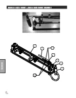
Page 56: ...54 Accessories 17 835 BOOM DRAWING ...

Page 57: ...14 17 596 Hinge Pin 2 HB 516 18 100 Bolt 5 16 18 x 1 2 15 17 541 Boom End Guard 2 HBFL 516 18 075 Bolt 5 16 18 x 3 4 4 HNFL 516 18 Flange Lock Nut 5 16 18 4 16 17 573 Guide Block Set 2 HB 14 20 125 Bolt 1 4 20 x 11 4 8 HNTL 14 20 Lock Nut 1 4 20 8 17 17 558 Right Boom Arm 1 18 33 506 Body see nozzle drawing 17 HB 516 18 075 Bolt 5 16 18 x 3 4 17 HNFL 516 18 Flange Lock Nut 5 16 18 17 19 17 559 Bre...

Page 58: ...BOOM MOUNT TO TRUCK REF PART DESCRIPTION QUANTITY A Center Boom Mount 1 B 17 614 Boom Spacer 2 C HB 516 18 100 Bolt 5 16 18 x 1 12 HNTL 516 18 Lock Nut 5 16 18 12 D 20 555 U Bolt 4 HNFL 12 13 Flange Lock Nut 1 2 13 8 ...

Page 59: ...6 x 1 6 HW 38 Washer 3 8 6 HNFL 38 16 Flange Lock Nut 3 8 16 6 5 18 417 Single Barb 2 6 18 416 Double Barb 3 7 33 506 Nozzle Body see nozzle drawing 5 8 18 415 3 4 T Hose Barb 1 9 9032 9 3 4 Black Hose x 9 3 18 040 Hose Clamp 6 10 9032 4 3 4 Black Hose x 4 2 18 040 Hose Clamp 4 11 HNFL 516 18 Flange Lock Nut 5 16 18 5 HB 516 18 075 Bolt 5 16 18 x 3 4 5 12 HB 38 16 250 Bolt 3 8 16 x 21 2 2 HNFL 38 ...

Page 60: ...way Mount 1 8 17 560 Hinge Mount 1 9 17 562 LH Break Away Arm 1 8946 3 5 Plastic Wear Strip 1 HRS 316 050 Steel Rivet 3 16 x 1 2 1 10 18 417 Single Barb 2 11 9032 28 3 4 Black Hose x 28 1 18 040 Hose Clamp 2 12 33 506 Nozzle Body see nozzle drawing 6 13 18 416 Double Barb 4 14 9032 4 3 4 Black Hose x 4 2 18 040 Hose Clamp 4 15 18 415 3 4 T Hose Barb 1 16 9032 9 3 4 Black Hose x 9 3 18 040 Hose Cla...

Page 61: ...rm 1 8 HB 14 20 125 Bolt 1 4 20 x 11 4 4 HNTL 14 20 Lock Nut 1 4 20 4 9 17 573 Guide Block Set 1 10 HBFL 516 18 075 Flange Bolt 5 16 18 x 3 4 4 HNFL 516 18 Flange Lock Nut 5 16 18 4 11 17 541 Boom End Guard 1 12 9032 4 3 4 Black Hose x 4 4 18 040 Hose Clamp 8 13 18 417 Single Barb 2 14 33 506 Nozzle Body see nozzle drawing 6 15 16 921 Cap 1 16 16 800 Seal 1 17 17 602 Body 1 18 18 416 Double Barb 5...

Page 62: ... 17 587 Boom Lock 1 2 HB 516 18 100 Bolt 5 16 18 x 1 4 HW 516 Flat Washer 5 16 2 HNTL 516 18 Lock Nut 5 16 18 4 3 42 116 Rubber Insert 2 4 8803 2 75 Trim black w lace 1 5 17 592 Lock Hinge LH 1 17 588 Lock Hinge RH 1 6 17 589 Limit Hinge RH 1 17 593 Limit Hinge LH 1 ...

Page 63: ...1 17 537 Square U bolt 1 2 HB 516 18 100 Bolt 5 16 18 x 1 8 HW 516 Washer 5 16 8 HNFL 516 18 Flange Lock Nut 5 16 18 8 3 17 636 Fresh Water Mount 1 4 HB 38 16 100 Bolt 3 8 16 x 1 2 HNFL 38 16 Flange Lock Nut 3 8 16 2 HW 38 Washer 3 8 2 5 17 635 Clean Load Mount 1 8803 13 Black Trim 13 1 ...

Page 64: ...es BOOM NEST ASSEMBLED REF PART DESCRIPTION QUANTITY 1 17 578 V Boom Nest Post 1 2 17 617 Boom Nest 2 3 HB 38 16 350 Bolt 3 8 16 x 31 2 2 HNTL 38 16 Lock Nut 3 8 16 2 4 18 297 Cap Plug 1 5 17 619 Round Push Plug 4 ...

Page 65: ...ubber Duct Hose x 2 2 3 17 527 Boom Hinge 1 4 17 539 Compression Spring 2 5 17 540 Tapped Bolt 2 6 HW 34 Washer 3 4 2 7 HNCL 34 10 Center Lock Nut 3 4 10 2 8 HG 14 28 180 Grease Zerk 3 9 17 591 Compression Spring 2 10 17 599 Spring Shim 2 11 17 594 Spring Sleeve 2 12 HB 38 16 100 Bolt 3 8 16 x 1 4 HNFL 38 16 Flange Lock Nut 3 8 16 4 ...

Page 66: ...1 3 HB 516 18 100 Bolt 5 16 18 x 1 2 HNFL 516 18 Flange Lock Nut 5 16 18 2 4 17 597 Torsion Spring RH 1 5 HB 12 13 500 Bolt 1 2 13 x 5 2 6 HP 18 100 Cotter Pin 1 8 x 1 2 7 30 214 KYB Actuator Complete 2 8 HB 12 13 300 Bolt 1 2 13 x 3 2 9 HNTL 12 13 Lock Nut 1 2 13 4 10 HB 38 16 100 Bolt 3 8 16 x 1 8 HNFL 38 16 Flange Lock Nut 3 8 16 8 ...

Page 67: ...ses The 45 cap must point towards the front of the machine and the tip opening must point toward the rear of the machine See Figure 1 If you need to rotate the 45 cap be advised it will not rotate all the way around You will need to rotate it right or left to get at other nozzles See Figure 2 33 541 triple Nozzle Kit for 15 Booms ...

Page 68: ...le Gray XR11006 VS 1 4 16 800 Viton Gasket 3 5 33 537 Cap Red 1 6 33 552 Nozzle Red XR11004 VS 1 7 33 554 Nozzle White XR11008 VS 1 8 16 802 Strainer 3 Quantity is per nozzle body For this boom multiply quantity by 17 Nozzles are located 10 24 5 cm apart on the right left and center tubes Nozzles are 20 high off ground ...

Page 69: ... 1 6 16 851 1 Nipple 1 7 18 448 1 Ball Valve 1 1 Thoroughly flush the service line upstream of the meter to remove dirt and debris 2 Set meter in line 3 Make sure the water flow follows the arrow cast on the meter body 4 The DLJ Meter is for use only with COLD WATER up to 122 F 50 C 5 Slowly open any upstream valves to prevent damage to the meter Gallons to Cubic feet Conversion Multiply gallons r...

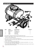
Page 70: ...68 Accessories 16 906 ELECTRIC HOSE REEL DRAWING ...

Page 71: ... 1 12 HWL 516 Lockwasher 5 16 8 13 Motor 12VDC 1 14 HW 516 Washer 5 16 4 15 33 252 Switch and Solenoid Brkt 1 HB 516 18 100 Bolt 5 16 18 x 1 2 HW 516 Washer 5 16 2 HWL 516 Lockwasher 5 16 2 HN 516 18 Nut 5 16 18 2 16 HNTL 516 18 Lock Nut 5 16 18 4 17 HB 516 18 100 Bolt 5 16 18 x 1 4 18 16 906 17 Key 1 19 Set Screw 2 20 16 906 29 Pinion 1 21 HNTL 38 16 Lock Nut 3 8 16 4 22 16 906 18 Frame Assembly ...

Page 72: ...70 Accessories 16 129 MANUAL HOSE REEL DRAWING ...

Page 73: ...Side 1 9 HWL 516 Lockwasher 5 16 8 10 HB 516 18 075 Bolt 5 16 18 x 3 4 8 11 16 129 09 Crank Assembly 3 4 1 12 16 129 10 Brake Assembly 3 4 1 13 HNTL 38 16 Lock Nut 3 8 16 4 14 HNTL 516 18 Lock Nut 5 16 18 2 15 16 129 08 Lock Pin Assembly 1 16 HB 516 18 075 Bolt 5 16 18 x 3 4 2 HW 516 Washer 5 16 2 17 16 129 07 Frame Assembly 1 18 16 906 08 Mounting Pillow Block Bottom 2 19 16 906 24 Bearing 2 20 1...

Page 74: ...er remain in tank as you will be taking apart lines 3 Remove key from ignition set park brake and block wheels 4 Install hose reel mount on the left side of the machine in front of the rear wheel Mount arms pointing to the rear of the machine 5 Use the u bolts to secure the mount to the machine 6 Put hose reel on hose reel bracket with fitting to the rear of machine Use four bolts 5 16 18 x 11 2 a...

Page 75: ...EPLACEMENT PROCEDURE 1 Facing swivel turn the hose drum clockwise until all of the hose is removed from the drum and the drum is held by locking mechanism Make sure spring is locked 2 Remove hose clamps and disconnect hose from swivel Remove old hose 3 Insert new hose through roller guide connect to swivel and reinstall hose clamps Use spring guard over hose to protect the hose from being cut by t...

Page 76: ... Type Fuse 30Amp 1 CONNECTION INSTRUCTIONS Route wire harness along side of tank and over to fuse block taking care to stay clear of moving parts or hot engine components Cut off excess wire and strip back 3 8 Place one 8963 heat shrink 1 4 x 11 4 on each wire before crimping 8901 slide on connectors to the red and white wires Connect the two wires to the fuse block first the red to the positive a...

Page 77: ...TIONS 1 Fresh Water Wash Tank mounts on the left side ROPs 2 Mount the wash tank Ref 3 onto the mount bracket Ref 1 using four 5 16 x 3 4 bolts washers and lock washers Ref 2 Tighten 3 Install the nipple Ref 5 elbow Ref 6 and spigot Ref 7 into the bottom of wash tank Ref 1 Use thread tape on all threads 4 Mount the tank ssembly to the left side ROPs with u bolts Ref 4 Tighten 5 Rinse tank with cle...

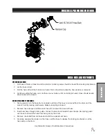
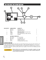
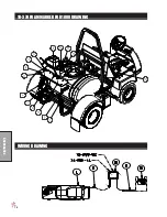
Page 78: ...76 Accessories 10 378 FOAM MARKER FOR 1000 DRAWING WIRING DRAWING ...

Page 79: ... facing the front of the machine using two 5 16 x 3 bolts Install the foamer plate Ref 5 on the right and left bracket with curve towards poly spray tank 5 Place the piece of trim Ref 14 on the foamer bracket to prevent rubbing of hoses for a clean load sys tem 6 Place foamer unit onto mount plate with cap facing to the right side of machine Using bolts and flange nuts bolt foam marker to mount pl...

Page 80: ...78 Accessories 10 378 FOAM MARKER DRAWING ...

Page 81: ...ALLATION HOSES Being careful not to cut the tubing cut the over sleeve back approximately 2 5 cm to expose blue and clear tubing Remove blue wing nut from top connector of foam nozzle and slide it on the blue tube with the threads facing toward end of tube Slide blue tube all the way over the top of the small tube on foam nozzle Slide wing nut back to the threads and hand tighten Follow the same s...

Page 82: ...80 Accessories FOAMER NOZZLE MOUNT HOSE GUARD MOUNT DRAWING ...

Page 83: ...e on foam nozzle Slide wing nut back to the threads and hand tighten Follow the same steps for the clear tube and tube nut 6 Route the tubing along underside of main frame using tie downs as necessary 7 Install opposite ends of air liquid tubes to compressor again cutting back the over sleeve approximately 2 5 cm and inserting blue and clear tubes for the left boom section into the tubing connecto...

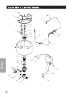
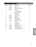
Page 84: ...82 Accessories 14 291 FOAMER REPLACEMENT PARTS ...

Page 85: ... Brush 1 10 15 505 07 12V Electric Motor 1 11 15 511 02 Foam Sponge 1 12 14 284 02 Cap Assembly 1 13 14 291 02 Foamer Tank 1 14 14 291 04 Tank Brackets 2 15 15 510 01 Nozzle Mounting Rod 2 16 16 987 Foam Nozzle Mounting Kit 1 17 14 284 09 Foam Nozzle Reducer 2 18 15 511 09 Stainless Steel Screen 2 19 15 511 08 Long Foam Sponge 2 20 15 511 Foam Nozzle 2 21 15 511 07 Foam Nozzle Assembly 1 22 15 511...

Page 86: ... mounts on the rear of all the machines 2 The Bracket is already attached to the Super Boom center boom post 3 Install the nipple Ref 2 elbow Ref 3 and spigot Ref 4 into the bottom of wash tank Ref 1 Use thread tape on all threads 4 Mount the tank onto the mount bracket using four 5 16 x 3 4 bolts washers and lockwashers Tighten 5 Rinse tank with clear water and check for leaks around fittings Thi...

Page 87: ... Clean load hopper Close and lock lid by turning cover clockwise Release the safety locking band on the hopper rinse ball valve and turn on for 20 seconds Close ball valve and return locking band to locked position 11 Open lid and inspect for chemical residue Repeat step 10 as necessary 12 Close knife valve by pulling red handle out towards you Turn inlet yellow handle off LOADING LIQUID AND OR PO...

Page 88: ...avy Boom on the Sprayer you will have to relocate the Chemical Clean load System and the Fresh Water tank There is a mount provided for you please see in the illustration 10 417 CHEMICAL CLEAN LOAD CLEAN LOAD FRESHWATER MOUNT ON 17 550 17 525 BOOMS ...

Page 89: ... 8 x 3 bolt flat washer top and bottom and lock nut 4 Bolt Clean load assembly onto mounting bracket using four flange bolts 5 16 18 x 3 4 and flange nuts Install 90 hose barb 16 156 into inlet side of Clean load valve with yellow handle then tighten so it points forward and down 5 Install one reducer coupling 18 391 and one 90 Hose Barb 16 156 onto the outlet side of Clean load Tighten so hose ba...

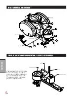
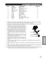
Page 90: ...88 Accessories 15 620 CHEMICAL CLEAN LOAD DRAWING ...

Page 91: ...rain Head 2 1 13 15 620 17 Gasket 2 Tapered 1 14 15 620 16 Locking Ring 2 1 15 15 620 12 Ball Valve 1 15 620 15 Gasket 2 BSP 1 16 15 620 13 Handle Clean load 1 17 1 2 MNPT PP Hex Plug 1 18 15 620 04 Clean load Eductor 1 20 15 620 14 Ball Valve 11 4 Single Union 1 21 Screw 2 22 Flange Nut 2 23 Hex Head Screw 2 24 15 620 01 Frame Back Mount 1 25 Phillips Head Screw 2 26 15 620 11 Elbow 1 2 2 28 15 6...

Page 92: ...4 1 FTP Elbow 1 4 16 158 Close Nipple 1 5 16 150 Double Thread Fitting 1 6 16 172 4 Nipple 1 7 15 834 Tank Rinsing Nozzle 1 8 16 163 Reducer Bushing 1 Drill 1 3 4 hole 5 from outside edge of cover Install Tank Rinsing kit as shown with the Double Thread Fitting Ref 5 going into the cover Basket Must be removed During Use ...

Page 93: ...ning Hot Tailpipe Guard D 25 286 Decal Crush Pinch Hood Back Edge Both Sides RH Control Panel E 15 719 Decal Speed Control LH Control Panel 27 093 Decal Oil Level LH Control Panel F 25 370 Decal 88 dba LH Front Panel 15 463 Decal Spray Pump LH Front Panel G 15 672 Decal Dash Panel Dash Board H 25 373 Decal Smithco Front Nose Cone I 27 077 Decal Smithco Steering Wheel J 10 414 Decal Control Panel R...

Page 94: ... 301 01 Repair Kit 77 263 Hydraulic Cylinder 14 530 Seal Kit 10 510 Wheel Motor 14 080 Seal Kit 42 797 Pump 14 098 Seal Kit 16 998 Hypro Pump 16 967 Silicone Carbon Seal Kit FLUIDS Engine Oil SAE 10W 40 API Service SJ or higher Motor Oil Hydraulic Fluid SAE 10W 40 API Service SJ or higher Motor Oil OTHER PARTS 14 532 Hinged Cover On Tank with Gasket 16 953 01 Gasket For Cover 16 169 Strainer Baske...

Page 95: ...afe operation of this product at your location Instructions for Obtaining Warranty Service You are responsible for notifying the Authorized Smithco Products Distributor from whom you purchased the Product as soon as you believe a warrantable condition exists and not later than 30 days from discovery of the condition If you need help locating an Authorized Smithco Distributor or if you have questio...

Page 96: ...ers if inspection by the original component manufacturer indicates that failure was due to normal wear and tear expected consumption through use or improper care or service Other Legal Disclaimers The above remedy for product defects through repair or replacement by an authorized Smithco distributor or dealer is the purchaser s sole remedy for any defect This warranty gives you specific legal righ...

Reviews: