Introduction
Ser
vice
Diagrams
Par
ts
Accessories
Reference
CONTENTS
Introduction ...................................................................1-3
Safe Practices ................................................................... 2
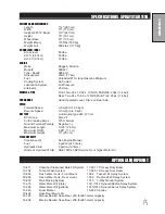
Specification
...................................................................... 3
Optional Equipment
........................................................... 3
Service ...........................................................................4-9
Maintenance
...................................................................4-6
Storage
.............................................................................. 6
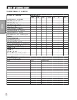
Service Chart ..................................................................... 7
End User’s Service Chart
.................................................. 8
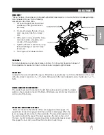
Adjustments
...................................................................... 9
Diagrams ...................................................................10-13
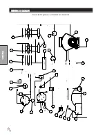
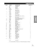
Wiring Diagram
........................................................... 10-11
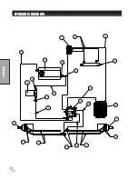
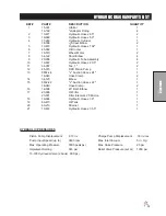
Hydraulic Diagram
......................................................12-13
Fitting Torque Charts
....................................................... 13
Parts...........................................................................14-43
Body and Frame
........................................................14-15
Control Panel
..............................................................16-17
Front Axle
..................................................................18-19
Seat Console and ROPS
............................................20-21
Fuel Tank
....................................................................22-23
Oil Tank-Oil Filter-Oil cooler
........................................24-25
Foot Pedal Linkage
.....................................................26-27
Pump
..........................................................................28-29
Engine and Spray Pump
.............................................30-31
Park Brake
..................................................................32-33
Rear Axle
....................................................................34-35
Spray Tank
..................................................................36-37
Turbo-Quad Agitator
...................................................36-37
15-301 Orbitrol
............................................................38-39
45-373 DDC20 Piston Pump
......................................40-41
16-998 Hypro
®
Pump
....................................................... 42
10-510 Wheel Motor
........................................................ 43
Accessories .......................................
44-114
1101Plumbing (Manual Valve)
....................................44-45
1104 Plumbing (TeeJet
®
744)
.....................................46-47
1102 Plumbing (TeeJet
®
Radion 8140)
.......................48-49
1104 Wiring(TeeJet
®
744)
................................................ 50
1102 Wiring (TeeJet
®
Radion 8140)
................................. 51
System Control Mounts
..............................................52-53
Star Command I & II Plumbing
...................................54-57
Star Command I Module Mounts
..................................... 58
Star Command I Wiring
................................................... 59
Star Commnad II Module Mounts
.................................... 60
Star Command II Wiring
.................................................. 61
20-817 Regulator l Valve
................................................. 62
15-737/14-628 Flanged Strainer
...................................... 63
10-648 3-Way Manual Valve
.......................................64-65
15-743 Manifold Ball Valve
............................................. 66
20-785 Regulator Valve
................................................... 67
14-801 Agitator Strainer
................................................... 68
17-585 18’ HD Boom
..................................................70-73
7-585 18’ HD 744 and Radion Plumbing
......................... 74
17-585 18’ HD Boom Star Command I Plumbing
............ 75
17-585 18’ HD Boom Star Command II Plumbing
........... 76
17-601 15’ HD Boom Star Command II Plumbing
........... 77
117-601 15’ HD Boom
................................................78-81
17-601 15’ HD Boom 744 and Radion Plumbing
............. 82
17-601 15’ HD Boom Star Command I Plumbing
............ 83
Star Command I Nozzle Assembly
.............................84-85
Standard Nozzle Assembly
.............................................. 86
Star Command II Nozzle Assembly
................................. 87
15-835 Tank Rinsing System
........................................... 88
10-370/10-365 Water Fill Meter Kit
.................................. 89
16-906 Electric Hose Reel
..........................................90-91
16-129 Hose Reel
............................................................ 92
10-422 Hose Reel Mount
(for HD Super Booms)
................ 93
Hose Reel Plumbing
...................................................94-95
Electric Hose Reel Wiring
................................................ 96
Hose Reel Adjustments
................................................... 97
10-740 Foam Marker Kit
..........................................98-103
14-291Foamer
........................................................104-105
30-006 Fresh Water Wash Tank -Rear Mount
............... 106
10-653 Fresh Water Wash Tank -Front Mount
.............. 107
10-734 16 Gallon Rinse Tank
.................................108-109
10-417 Chemical Cleanload
®
...................................110-111
15-620 Chemical Cleanload
®
Eductor
.................... 112-113
Chemical Cleanload Instructions
................................... 114
Reference .......................................115-116
Decal List
....................................................................... 115
Quick Reference Replacement Parts
............................ 116
Summary of Contents for 10-100-F
Page 12: ...10 Diagrams WIRING DIAGRAM Use dielectric grease on all electrical connections ...
Page 14: ...12 Diagrams HYDRAULIC DIAGRAM ...
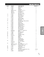
Page 16: ...14 Parts MAIN BODY DRAWING ...
Page 18: ...16 Parts CONTROL PANEL DRAWING ...
Page 20: ...18 Parts FRONT AXLE DRAWING ...
Page 22: ...20 Parts SEAT CONSOLE DRAWING ...
Page 24: ...22 Parts FUEL TANK DRAWING ...
Page 26: ...24 Parts OIL TANK OIL FILTER OIL COOLER DRAWING ...
Page 28: ...26 Parts FOOT PEDAL LINKAGE DRAWING ...
Page 30: ...28 Parts PUMP DRAWING ...
Page 32: ...30 Parts ENGINE AND SPRAY PUMP DRAWING ...
Page 34: ...32 Parts PARK BRAKE DRAWING ...
Page 36: ...34 Parts REAR AXLE DRAWING ...
Page 38: ...36 Parts TANK DRAWING TURBO QUAD AGITATOR DRAWING ...
Page 40: ...38 Parts 15 301 ORBITAL DRAWING ...
Page 42: ...40 Parts 45 373 DDC20 PISTON PUMP DRAWING ...
Page 54: ...52 Accessories CONTROL MOUNTS ...
Page 61: ...59 Accessories STAR COMMAND I WIRING 10 716 M ...
Page 66: ...64 Accessories 10 648 3 WAY MANUAL VALVE DRAWING ...
Page 71: ...69 Accessories NOTES ...
Page 72: ...70 Accessories 17 585 18 HD BOOM DRAWING ...
Page 74: ...72 Accessories 17 585 18 HD BOOM DRAWING ...
Page 80: ...78 Accessories 17 601 15 HD BOOM DRAWING ...
Page 82: ...80 Accessories 17 601 15 HD BOOM DRAWING ...
Page 92: ...90 Accessories 16 906 ELECTRIC HOSE REEL DRAWING ...
Page 104: ...102 Accessories FOAMER NOZZLE MOUNT DRAWING ...
Page 106: ...104 Accessories 14 291 FOAMER REPLACEMENT PARTS ...
Page 112: ...110 Accessories 10 417 CHEMICAL CLEAN LOAD TROUBLE SHOOTING ...
Page 114: ...112 Accessories 15 620 CHEMICAL CLEAN LOAD DRAWING ...

