background image

67

Accessories

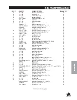
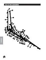
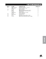
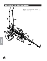
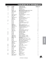
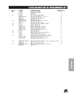
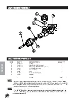
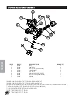
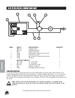
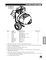
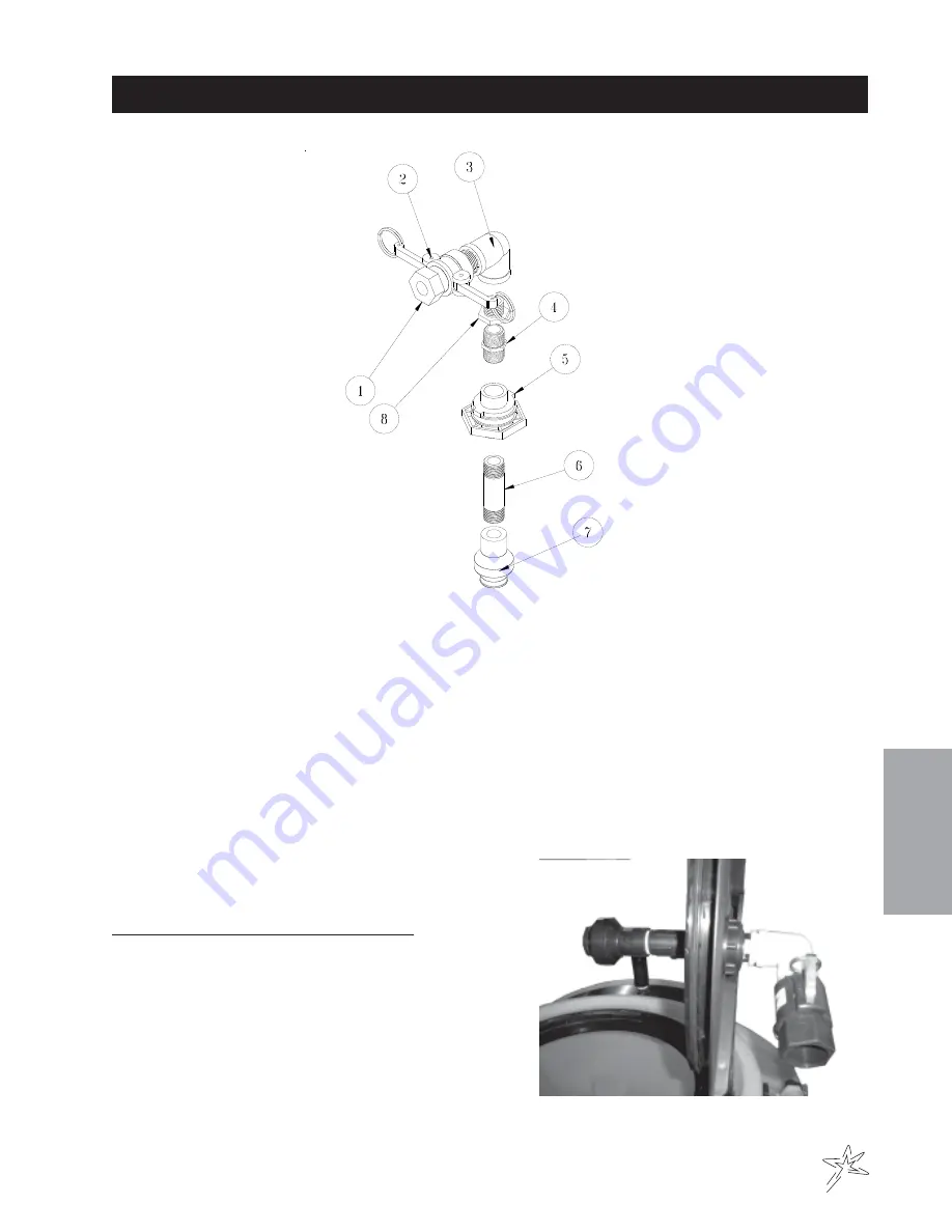
15-835 TANK RINSING  SYSTEM

REF#PART#

DESCRIPTION

QUANTITY

1

16-961

1" Adapter

1

2

16-962

1" Coupler

1

3

16-864

1" FTP Elbow

1

4

16-158

Close Nipple

1

5

16-150

Double Thread Fitting

1

6

16-172

4" Nipple

1

7

15-834

Tank Rinsing Nozzle

1

8

16-163

Reducer Bushing

1

Drill 1-3/4" hole 5" from outside edge of cover.

Install Tank Rinsing kit as  shown, with the Double Thread
Fitting (Ref 5) going into the cover.

Basket Must be removed During Use.

Summary of Contents for 17-500

Page 1: ...Product Support Hwy SS Poplar Ave Cameron WI 54822 1 800 891 9435 productsupport smithco com Parts Service Spray Star 1750D Diesel Model 17 500 SN 175GD078 November 2008 Revised August 2009 ...

Page 2: ... 45 Controls 1752D System Raven 440 46 Control 1754D System Raven 203 47 16 524 Motorized Control Valve 48 15 737 Strainer 49 15 743 Manifold Ball Valve 50 17 503 20 Spray Boom 52 55 15 493 Stainless Steel 18 Auto Boom 56 59 Nozzle Assembly 60 Turbo TurfJet Tips 61 XR TEEJET Tips 61 17 525 18 5 HD Super Boom 62 63 17 550 15 HD Super Boom 64 65 Triple Nozzle Asembly 66 15 835 tank Rinsing System 67...

Page 3: ...ructions Failure to do so could result in personal injury or equipment dam age Keep manuals in a safe place after operator and maintenance personnel have read them Right and left sides are from the operator s seat facing forward All machines have a Serial Number and Model Number Both numbers are needed when ordering parts The serial number plate on the Spray Star 1750 is located on the left main f...

Page 4: ...k brake before starting the engine 12 Never use your hands to search for oil leaks Hydraulic fluid under pressure can penetrate the skin and cause serious injury 13 This machine demands your attention To prevent loss of control or tipping of the vehicle A Use extra caution in backing up the vehicle Ensure area is clear B Do not stop or start suddenly on any slope C Reduce speed on slopes and in sh...

Page 5: ...ive type 24F 12 volt BCI Group Size 24 Cold CrankingAmps 900 minimum Ground Terminal Polarity Negative Maximum Length 10 25 26 cm Maximum Width 6 88 17 cm Maximum Height 10 25 cm FLUIDCAPACITY Crankcase Oil See Engine Manual Fuel 7 gallon 26 5 liters Hydraulic Fluid 5 gallon 19 liters Grade of Hydraulic Fluid SAE 10W 40 API Service SJ or higher OPTIONALEQUIPMENT 15 618 Water Meter Kit Liters 14 51...

Page 6: ...er front pivot D One on the idler arm E One on the brake relay F One on each of the pedal relays G One on the shift arm ELECTRICALCONNECTIONS Use dielectric grease on all electrical connections AIRCLEANERONENGINE 1 Unclip the two clips remove the cover and pull out the element 2 To service clean by tapping gently on flat surface Do not oil Replace if very dirty or damaged 3 Clean out the inside of...

Page 7: ...reme caution when filling hydraulic oil tank or checking level to keep system free of contaminants Check and service more frequently when operating in extremely cold hot or dusty condi tions 6 If the natural color of the fluid has become black or smells burnt it is possible that an overheating problem exists 7 If fluid becomes milky water contamination may be a problem 8 If either of the above con...

Page 8: ...minutes or 7 amps for 30 minutes Do not exceed the recommended charging rate If electrolyte starts boiling over decrease charging Always remove grounded battery clamp first and replace it last Avoid hazards by 1 Filling batteries in well ventilated areas 2 Wear eye protection and rubber gloves 3 Avoid breathing fumes when electrolyte is added 4 Avoid spilling or dripping electrolyte Battery Electr...

Page 9: ...e oil Check the hydraulic fluid level Check the tire pressure Check condition of hydraulic hoses and fittings Inspect and clean the machine Inspect cooling system Check the battery fluid level and cable connections Change oil when operating under heavy load or high ambient temperatures Change the engine oil and filter Change hydraulic filter Check engine for leaks or loose parts Check air cleaner ...

Page 10: ... cooling fins Check for unusual engine noises Check the hydraulic oil level Check hydraulic hoses and fittings for damage Check for fluid leaks Check the tire pressure 5 psi Check the Instrumentation Inspect electrical system for frayed wires Check park brake adjustment Change oil filter Change oil Lubricate Machine Ensure all warning decals are intact Item For the week of Maintence Check Item Are...

Page 11: ...se on end of park brake to tighten Turn it counter clockwise to loosen If finer adjustment is needed turn clevis on brake cable to adjust length of cable SPEEDCALIBRATIONNUMBERS The speed calibration numbers for the Spray Star 1752 is 612 STORAGE If the engine will be out of service for two or more months use the following storage procedure 1 Clean the exterior surfaces of the engine 2 Change the ...

Page 12: ... 782 Rocker Switch Unlit 1 9 15 729 Mount Panel Middle 1 15 726 Switch Body Light 1 15 732 Actuator Green 1 10 15 729 Mount Panel Middle 1 15 726 Switch Body Light 1 15 731 Actuator Amber 1 11 15 729 Mount Panel Middle 1 15 727 Switch Actuator 1 15 728 Switch Body On Off On 1 12 15 725 Mount Panel End 1 15 727 Switch Actuator 1 15 728 Switch Body On Off On 1 Use dielectric grease on all electrical...

Page 13: ... 33 509 Cruise Foot Switch 1 19 30 107 Wire Harness Battery Ground to Fuse 1 20 33 084 Magnetic Coil 1 21 76 327 Ground Battery Cable 1 22 33 216 Battery 1 23 30 106 Wire Harness Battery to Fuse 1 24 48 157 Positive Battery Cable 1 25 16 883 Speed Sensor 1 26 77 261 Circuit Breaker 40 amp 1 8977 Boot 1 NA 15 789 Main Wire Harness 1 Color Code Chart Bl Blue Br Brown Y Yellow G Green O Orange R Red ...

Page 14: ...12 Diagrams HYDRAULICDIAGRAM ...

Page 15: ...ion Hose 2 18 040 Hose Clamp 4 6 75 714 Hydraulic Cylinder 1 7 15 687 Hydraulic Hose 751 2 2 8 15 301 Orbitrol 1 9 15 686 Hydraulic Hose 1071 2 1 10 60 473 Hydraulic Oil tank 1 11 8917 26 3 8 Suction Hose 1 18 040 Hose Clamp 2 12 26 016 Oil Filter 1 23 031 Replacement Filter 1 13 42 045 Hydraulic Hose 1 14 77 239 Hydrostatic Pump 1 15 30 098 Gear Pump 1 16 15 624 Cooler 1 17 15 683 Hydraulic Hose ...

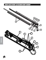
Page 16: ...14 Parts BODY FRAMEDRAWING ...

Page 17: ...2 12 7 15 762 Roll Bar 1 8 15 710 LH Boom Holder 1 9 15 756 Back Panel 1 10 14 519 Seat 1 11 15 709 RH Boom Holder 1 12 15 822 Nose Cone fiberglass 1 17 524 Oval Lights 2 10 421 Pigtail 1 13 15 751 RH Step 1 15 752 LH Step 1 14 15 823 RH Front Fender 1 15 767 LH Front Fender 1 15 16 857 Tire and Wheel 2 16 857 01 Tire 20 x 10 00 10NHS 4 Ply 2 16 857 02 Wheel 2 16 HB 12 13 200 Bolt 1 2 13 x 2 8 HW ...

Page 18: ...16 Parts NOSE CONE DRAWING ...

Page 19: ...lt Steering Column 1 18 HB 516 18 125 Bolt 5 16 18 x 11 4 4 HW 14 Washer 1 4 4 HNFL 516 18 Flange Lock Nut 5 16 18 4 19 HBM 6 1 16 Metric Bolt 4 HWLM 6 Metric Lock Washer 4 20 15 754 Dash Panel 1 30 017 Decal Dashboard 1 21 Lights 15 725 Mount Panel End 1 15 727 Switch Actuator 1 15 782 Rocker Switch Unlit 1 22 Cruise Control 15 729 Mount Panel Middle 1 15 726 Switch Body Light 1 15 732 Actuator G...

Page 20: ...18 Parts NOSE CONE DRAWING ...

Page 21: ...6 18 150 Machine Screw 5 16 18 x 11 2 7 HNFL 516 18 Flange Lock Nut 5 16 18 7 33 15 752 Left Step 1 34 15 820 Foot Pedal Assembly 1 HG 14 28 180 Grease Fitting 1 4 28 x 180 2 HMB 12 14 Machine Bushing 1 2 x 14GA 5 35 HSSHS 5 16 18 038 Socket Head Set Screw 5 16 18 2 36 15 821 Reverse Pedal 1 37 76 332 Pedal Pad 1 38 15 760 Short Foot Pedal Rod 1 39 15 692 Pedal Relay 1 33 084 Magnetic Coil 1 40 21...

Page 22: ...20 Parts FRONT AXLE DRAWING ...

Page 23: ... 18 1 15 HCP 58 175 Clevis Pin 5 8 x 13 4 1 HP 18 100 Cotter Pin 1 8 x 1 1 16 75 714 Hydraulic Cylinder 1 18 168 Elbow 2 14 254 Seal Kit 17 HB 58 11 250 Bolt 5 8 11 x 21 2 3 18 18 154 Rod End 3 19 16 883 Magnetic Sensor 1 HNJ 34 16 Jam Nut 3 4 16 1 20 10 265 Hub with Sprocket 1 HSSHS 516 18 038 Socket Head Set Screw 5 16 18 x 3 8 2 21 16 076 King Pin 2 22 15 695 Spindle RH 1 23 HNTL 58 11 Lock Nut...

Page 24: ...22 Parts OILANDFUELTANKDRAWING ...

Page 25: ...1 10 HB 14 20 075 Bolt 1 4 20 x 3 4 2 HW 14 Washer 1 4 2 HWL 14 Lock Washer 2 11 Part of Main Frame 12 26 016 Oil Filter 1 13 18 008 Pipe Thread Reducer 1 14 23 143 Connector 1 15 23 031 Replacement Filter 1 16 73 049 7 Gallon Fuel Tank 1 17 73 050 Cap with Gauge 1 18 HB 14 20 125 Bolt 1 4 20 x 3 4 2 HNFL 14 20 Flange Loc Nut 1 4 20 2 19 73 051 Gas TAnk Strap 2 20 15 824 Tank Mount 1 21 75 792 Tan...

Page 26: ...24 Parts SEATPANEL DRAWING ...

Page 27: ... Screw 10 32 x 5 8 12 HN 10 32 Nut 10 32 12 14 15 786 Hood Rod 1 HW 38 Washer 3 8 4 HP 18 075 Cotter Pin 1 8 x 3 4 2 15 80 020 Choke Cable 1 16 34 160 Throttle Cable 1 34 160 01 Inner Cable 1 17 15 711 Front Panel 1 HBFL 516 18 075 Flange Bolt 5 16 18 x 3 4 2 HNFL 516 18 Flange Nut 5 16 18 2 18 60 106 Park Brake 1 19 15 751 Step RH 1 15 752 Step LH 1 20 15 823 Front Fender RH 1 21 16 857 Tire and ...

Page 28: ...26 Parts ENGINE PUMPSANDEXHAUSTDRAWING ...

Page 29: ...3 188 Male Connector 3 8 1 22 30 098 Gear Pump 1 23 HB 38 16 125 Bolt 3 8 16 x 11 4 4 HW 38 Washer 3 8 4 HWL 38 Lock Washer 3 8 4 24 23 127 Adjustable Elbow 1 25 23 130 Elbow 1 26 15 702 Adapter 1 27 15 693 Shift Arm 1 HSSHS 14 20 031 Socket Head Set SCrew 1 4 20 x5 16 1 28 HB 38 16 200 Bolt 3 8 16 x 2 1 HW 38 Washer 3 8 5 HWL 38 Lock Washer 3 8 1 HN 38 16 Nut 3 8 16 1 29 14 266 Ball Bearing 1 42 ...

Page 30: ...28 Parts ENGINE PUMPSANDEXHAUSTDRAWING ...

Page 31: ...16 18 x 1 4 HBFL 516 18 075 Bolt 5 16 18 x 3 4 4 HNFL 516 18 Flange Whiz Lock Nut 5 16 18 8 40 43 122 Muffler 1 41 15 805 Rear Engine Plate 1 42 HB 12 13 150 Bolt 1 2 13 x 11 2 2 HW 12 Washer 1 2 2 HNFL 12 13 Flange Whiz Lock Nut 1 2 13 2 43 50 111 Muffler Clamp 1 44 15 809 Exhaust Elbow 1 45 15 791 Engine B S 954T Turbo Diesel 1 21 161 Wire Block 1 46 HBM 6 1 16 Metric Hex Bolt M6 1 x 16 4 HWLM 6...

Page 32: ...30 Parts SPRAYPUMPDRAWING ...

Page 33: ...HW 38 Washer 3 8 2 HNL 38 16 Flnage Lock Nut 3 8 16 2 9 15 800 Belt Guard 1 10 15 798 Belt Guard Mount 1 11 16 998 Spray Pump 1 12 16 156 Elbow 1 13 18 372 3 Way Valve 1 18 372 01 T Handle 1 14 16 935 Quick Coupler Cap 1 15 16 180 Quick Coupler Male 1 16 16 161 Fitting 2 17 8897 19 Discharge Hose 11 4 x 19 1 18 222 Hose Clamp 2 18 16 825 Hex Bushing 1 19 33 494 Male Elbow 1 20 33 480 Pressure Swit...

Page 34: ...32 Parts TANKDRAWING TURBO QUADAGITATORDRAWING ...

Page 35: ...1 Main Frame 1 17 16 998 Hypro Pump 1 18 33 494 Male Elbow 2 19 HB 12 13 125 Bolt 1 2 13 x 11 4 4 HNFL 12 13 Flange Nut 1 2 13 4 20 16 156 Elbow 1 21 16 194 11 4 Anti Vortex Fitting part of tank 1 22 8954 30 Clear Hose 3 16 1 23 33 496 Reducer Bushing 1 2 to 1 8 1 24 33 495 Bulkhead Fitting 1 25 14 451 Spray Tank 1 16 169 Strainer Basket 1 26 15 787 Hood Support 1 27 50 081 Rubber Bumper 1 HNFL 38...

Page 36: ...34 Parts PARKBRAKEANDREARAXLEDRAWING ...

Page 37: ... Pad Kit 1 10 76 239 Brake Disc 5 hole 2 11 76 238 Wheel Motor 2 HMB 12 14 Machine Bushing 1 2 x 14GA 4 12 HB 12 13 800 Bolt 1 2 13 x 8 4 HNFL 12 13 Flange Lock Nut 1 2 13 4 13 HB 12 13 750 Bolt 1 2 13 x 71 2 4 HNFL 12 13 Flange Lock Nut 1 2 13 4 14 15 681 Hydraulic Hose 4 15 34 057 Tee 2 16 15 700 RearAxle 1 17 HBFL 516 18 075 Flange Bolt 5 16 18 x 3 4 8 HNFL 516 18 Flange Nut 5 16 18 8 18 HWK 51...

Page 38: ...36 Parts 15 301 ORBITROL DRAWING ...

Page 39: ...1 08 Drive Pin 1 15 Spool 1 16 Spring Retaining Ring 1 17 10 576 05 Gerotor 1 18 O Ring 1 19 Seal Ring 1 20 15 301 03 End Cap 1 21 10 576 06 Cap Screw 7 15 301 01 Seal Kit 1 15 301 15 Centering Spring Kit 1 15 301ORBITROLSPECIFICATIONS Inlet Relief Valve Setting 1020 psi 70 bar Nominal Flow 3 gpm 11 lpm Displacement 4 50 cu in R 73 8 cu cm R Check Valve for Manual Steering Yes Inlet Pressure Ratin...

Page 40: ...38 Parts 77 239 EATON HYDROSTATIC PUMP DRAWING DIESEL ...

Page 41: ...0 Crush Ring 1 14 60 343 12 Shaft Seal 1 15 77 239 11 Seal Cover 1 16 77 239 12 Key 1 17 77 239 13 Gasket 1 18 77 239 14 Back Plate 1 19 33 058 27 Dowel Pin 2 20 60 343 23 Bearing 1 21 77 239 15 Relief Valve 4000 psi 2 22 77 239 16 Tow Valve Assembly 1 23 76 160 Charge Pump Adaptor 1 24 77 239 17 Cap Screw 2 25 77 130 O Ring mounting kit 1 26 77 239 18 Cap Screw 2 27 77 239 19 O Ring 1 28 60 343 4...

Page 42: ...40 Parts 16 998 HYPRO PUMP DRAWING ...

Page 43: ...cal Seal Silicon Carbide 1 8 16 966 06 Slinger Ring 1 9 16 998 06 Mounting Flange 1 11 16 998 07 Bolt 4 12 16 966 10 Ball Bearing 2 13 16 998 08 Key 1 14 16 998 09 Pump Shaft 1 15 16 822 20 Key 1 16 16 966 13 Bearing Retainer 1 17 16 998 10 Gasket 1 18 16 994 01 Clutch 1 16 967 Silicone Carbon Seal Kit When servicing the spray pump or filter all control valves must be shut off if there is liquid i...

Page 44: ...42 Accessories 1752D PLUMBING DRAWING RAVEN 440 ...

Page 45: ...Series Clamp 2 17 15 738 Flanged Ball Valve 1 18 15 808 Flange Hose Barb Straight 1 19 8896 55 1 Suction Hose 55 1 18 116 Hose Clamp 1 18 040 Hose Clamp 1 20 16 156 Elbow 3 21 18 372 3 Way Valve 1 18 372 01 T Handle 1 22 16 180 Quick Coupler Male 1 23 16 935 Quick Coupler Cap 1 24 16 161 Fitting 2 25 8897 38 11 4 Discharge Hose 38 1 18 116 Hose Clamp 2 26 16 825 Hex Bushing 1 27 16 998 Pump 1 28 1...

Page 46: ...44 Accessories 1754D PLUMBING DRAWING RAVEN 203 ...

Page 47: ...ge Nut 3 8 16 2 16 15 780 Poly Hex Plug 1 17 15 737 Flanged Strainer 1 18 15 735 50 1 FTP Fitting 1 19 15 808 Flanged Hose Barb Straight 1 20 15 738 Fllanged Ball Valve 1 21 8897 70 11 4 Discharge Hose 70 1 18 116 Hose Clamp 2 22 16 156 Elbow 3 23 8896 55 1 Suction Hose 55 1 18 116 Hose Clamp 1 18 040 Hose Clamp 1 24 18 372 3 Way Valve 1 18 372 01 T Handle 1 25 16 180 Quick Coupler Male 1 26 16 93...

Page 48: ... 4 10 202 Speedometer 1 5 10 408 01 Phoenix 10 GPS 1 6 15 743 Manifold Ball Valve 1 7 16 524 Motorized Control Valve 1 8 18 373 Flow Meter 1 9 15 369 Console Control Cable 1 10 33 271 Fuse Block 1 11 33 273 Auto Blade Type Fuse 30 amp 1 12 33 508 Auto Blade Type Fuse 15 amp 1 13 33 509 Master boom Switch 1 15 758 Floor Plate 1 Use Dielectric Grease On All Electrical Connections ...

Page 49: ...se Holder 1 16 525 03 Fuse 15 AMP 1 8 16 895 Pressure Switch 1 9 16 902 Cable Assembly 6ft Enclosure Hook Up 1 10 16 958 05 Union Fitting 1 11 16 524 Motorized Control Valve 1 12 15 743 Manifold Valve 1 13 15 775 Tee 1 14 16 955 Tubing 1 15 16 902 Cable Assembly 72 Solenoid Hook Up 1 16 33 271 Fuse Block 1 17 33 508 Auto Blade Type Fuse 15 amp 1 18 10 225 Wire Harness fuse block to electric valve ...

Page 50: ... run or if the printed circuit board is corroded Before reassembling valve remove the coupler shaft from the valve body Apply Loctite to coupler shaft and woodruff key Place the coupler shaft Ref 7 and the woodruff key Ref 5 onto the motor shaft Plug motor into the valve connector coming from Sprayer Control Console Check that the motor rotates in both directions Motor must stop when coupler CAM r...

Page 51: ...15 737 STRAINER REF PART DESCRIPTION QUANTITY 1 15 737 01 Strainer Head 75 Series 1 2 16 968 03 50 MEsh Strainer 1 3 14 521 02 EPDM Gasket 1 4 14 521 03 Bowl 1 NPT 1 5 14 521 04 EPDM Rubber gasket 1 6 14 521 05 Cap 1 ...

Page 52: ...17 11 Thrust Washer Teflon 1 6 15 552 27 Stem Stainless Steel 1 7 15 552 05 O ring Viton 3 8 15 517 16 Body Nylon 1 9 15 517 17 Dust Plug Felt 1 10 Lock Nut Stainless Steel 2 11 15 743 04 Ball Polypropylene 1 12 15 552 13 Gasket Viton 2 13 15 517 19 Seal teflon 2 14 15 517 20 O ring Viton 2 15 15 743 01 End Cap 1 16 15 743 03 Mounting Rail aluminum 1 17 15 743 02 75 Tee Body 1 15 552 10 Spare Past...

Page 53: ...51 Accessories NOTES ...

Page 54: ...52 Accessories 17 503 20 SPRAY BOOM DRAWING ...

Page 55: ...332 Right Brush Guard 1 17 16 024 U Bolt 5 16 24 6 HWLS 516 Stainless Steel Lockwasher 5 16 12 HNS 516 24 Stainless Steel Nut 5 16 24 12 18 16 928 Right and Left Tube 2 19 16 996 Nozzle Bodies 12 20 33 301 Right Pivot Bracket 1 21 15 813 Pivot Bracket 2 15 494 Nylon Flange Bushing part of 15 813 4 18 036 Oilite Bushing part of 15 813 4 HSSQS 38 16 150 Stainless Steel Set Screw 3 8 16 x 11 2 2 HN 3...

Page 56: ...54 Accessories 17 503 20 SPRAY BOOM DRAWING ...

Page 57: ... 2 13 2 30 15 495 Extension Spring 2 31 15 812 Right Cam Stop must also order 15 811 2 15 811 Left Cam Stop must also order 15 812 2 18 268 Oilite Bushing 2 HMB 100 10 Machine Bushing 1 x 10GA 2 32 33 302 Left Pivot Bracket 1 33 HPS 18 100 Cotter Pin 3 8 x 1 2 34 18 411 Stainless Steel Pipe Elbow 3 4 x 45 2 35 11 180 Right hand LinearActuator with 4 Stroke 1 ...

Page 58: ...56 Accessories 15 493STAINLESSSTEEL18 AUTOBOOM DRAWING 8887 120 Orange Hose Right Left Booms 3 18 040 Hose Clamps 6 ...

Page 59: ...8 Stainless Steel Washer 3 8 4 HNTL 38 16 Lock Nut 3 8 16 4 13 16 024 U Bolt 5 16 24 6 HWLS 516 Stainless Steel Lockwasher 5 16 12 HNS 516 24 Stainless Steel Nut 5 16 24 12 14 33 332 Right Brush Guard 1 15 16 928 Right and Left Tube 1 16 16 966 Nozzle Bodies 11 17 33 301 Right Pivot Bracket 1 HMB 100 14 Machine Bushing 1 x 14GA 2 HMB 100 10 Machine Bushing 1 x 10GA 1 HRPS 14 150 Stainless Steel Ro...

Page 60: ...58 Accessories 15 493STAINLESSSTEEL18 AUTOBOOMDRAWING ...

Page 61: ...x 45 2 34 33 302 Left Pivot Bracket 1 HMB 100 14 Machine Bushing 1 x 14GA 2 HMB 100 10 Machine Bushing 1 x 10GA 1 HRPS 14 150 Stainless Steel Roll Pin 1 4 x 11 2 2 35 15 495 Extension Spring 2 36 15 811 Left Cam Stop must also order 15 812 2 18 268 Oilite Bushing part of 15 811 2 37 11 158 Left hand LinearActuator with 4 Stroke 1 HCPS 12 225 Stainless Steel Clevis Pin 1 2 x 21 4 2 HPS 18 100 Stain...

Page 62: ...er 16 996 Body 1 When the 16 920 05 Teflon Diaphragm is used it is placed in the assembly in front of the 16 920 06 EPDM Rubber Diaphragm Nozzles are located 20 51 cm apart on the right left and center tubes There are predrilled holes in all tubes The Nozzle should be at a 45 angle to the ground for proper application For all 18 Booms The eleven 16 996 bodies are installed on the boom sections The...

Page 63: ...ed If a decision to tilt the nozzle is made do it before measuring the width of the spray on the ground and adjust ing nozzle height See example below DRIFTABLE FINES PRODUCED 0 5 gpm at 40 psi Nozzle Percent of Spray Volume 5 gpm Output less than 200 microns Turbo TurfJet 1 XR TEEJET TIPS This is an extended range flat spray tip It is excellent for Contact Pesticides and Growth Regulators and goo...

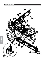
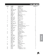
Page 64: ...62 Accessories 17 525 HEAVYBOOM ...

Page 65: ...7 532 Right Boom Arm 1 13 HSSQS 38 16 150 Square Head Set SCrew 3 8 16 x 11 2 2 14 33 506 Body see nozzle drawing 11 HB 516 18 075 Bolt 5 16 18 x 3 4 11 HNFL 516 18 Flange Lock Nut 5 16 18 11 15 17 527 Boom Hinge 4 HB 38 16 100 Bolt 3 8 16 x 1 16 HNFL 38 16 Lock Nut 3 8 16 16 16 17 539 Compression Spring 4 17 9026 2 Rubber Duct Hose x 2 4 18 17 540 Tapped Bolt 4 HW 34 Washer 3 4 4 HNTL 34 10 Lock ...

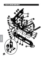
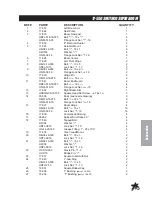
Page 66: ...64 Accessories 17 55015 SMITHCOSUPERBOOM ...

Page 67: ...17 552 Right Boom Arm 1 13 HSSQS 38 16 150 Square Head Set Screw 3 8 16 x 11 2 2 14 33 506 Body see nozzle drawing 9 HB 516 18 075 Bolt 5 16 18 x 3 4 9 HNFL 516 18 Flange Lock Nut 5 16 18 9 15 17 527 Boom Hinge 4 HB 38 16 100 Bolt 3 8 16 x 1 16 HNFL 38 16 Lock Nut 3 8 16 16 16 17 539 Compression Spring 4 17 9026 2 Rubber Duct Hose x 2 4 18 17 540 Tapped Bolt 4 HW 34 Washer 3 4 4 HNTL 34 10 Lock Nu...

Page 68: ...6 802 Strainer 1 Quantity is per nozzle body For 18 booms multiply quantity by 11 Quantity is per nozzle body For 15 booms multiply quantity by 9 Nozzles are located 20 51 cm apart on the right left and center tubes There are predrilled holes in all tubes The Nozzle should be at a 45 angle to the ground for proper application For re ordering Nozzle Kits the following numbers apply 33 540 Triple No...

Page 69: ... 1 FTP Elbow 1 4 16 158 Close Nipple 1 5 16 150 Double Thread Fitting 1 6 16 172 4 Nipple 1 7 15 834 Tank Rinsing Nozzle 1 8 16 163 Reducer Bushing 1 Drill 1 3 4 hole 5 from outside edge of cover Install Tank Rinsing kit as shown with the Double Thread Fitting Ref 5 going into the cover Basket Must be removed During Use ...

Page 70: ...68 Accessories 16 906ELECTRICHOSEREELDRAWING ...

Page 71: ...asher 5 16 4 15 33 252 Switch and Solenoid Brkt 1 HB 516 18 075 Bolt 5 16 18 x 3 4 2 HW 516 Washer 5 16 2 HWL 516 Lockwasher 5 16 2 HN 516 18 Nut 5 16 18 2 16 HNTL 516 18 Lock Nut 5 16 18 4 17 HB 516 18 100 Bolt 5 16 18 x 1 4 18 16 906 17 Key 1 19 Set Screw 2 20 16 906 29 Pinion 1 21 HNTL 38 16 Lock Nut 3 8 16 4 22 16 906 18 Frame Assembly 1 23 16 906 08 Mounting Pillow Block Bottom 2 24 16 906 24...

Page 72: ...NINSTRUCTIONS Route wire harness along side of tank and over to fuse block taking care to stay clear of moving parts or hot engine components Cut off excess wire and strip back 3 8 Place one 8963 heat shrink 1 4 x 11 4 on each wire before crimping 8901 slide on connectors to the red and white wires Connect the two wires to the fuse block first the red to the positive and the white to the negative ...

Page 73: ...oved HOSE REPLACEMENT PROCEDURE 1 Facing swivel turn the hose drum clockwise until all of the hose is removed from the drum and the drum is held by locking mechanism Make sure spring is locked 2 Remove hose clamps and disconnect hose from swivel Remove old hose 3 Insert new hose through roller guide connect to swivel and reinstall hose clamps Use spring guard over hose to protect the hose from bei...

Page 74: ...72 Accessories 16 129MANUALHOSEREELDRAWING ...

Page 75: ...8 x 3 4 8 11 16 129 09 Crank Assembly 3 4 1 12 16 129 10 Brake Assembly 3 4 1 13 HNTL 38 16 Lock Nut 3 8 16 4 14 HNTL 516 18 Lock Nut 5 16 18 2 15 16 129 08 Lock Pin Assembly 1 16 HB 516 18 075 Bolt 5 16 18 x 3 4 2 HW 516 Washer 5 16 2 17 16 129 07 Frame Assembly 1 18 16 906 08 Mounting Pillow Block Bottom 2 19 16 906 24 Bearing 2 20 16 906 07 Mounting Pillow Block Top 2 21 16 906 23 SwivelAssembl...

Page 76: ...k and taking apart the lines 2 Drain tank and spray system in a safe and approved method insuring that no chemical or water remain in tank as you will be taking apart lines 3 Remove key from ignition set park brake and block wheels 4 Install hose reel mount on the left side of the machine over the rear wheel 5 Use the clamps and bolts to secure the mount to the machine 6 Put hose reel on hose reel...

Page 77: ...g when draining the tank and taking apart the lines 2 Drain tank and spray system in a safe and approved method insuring that no chemical or water remain in tank as you will be taking apart lines 3 Remove key from ignition set park brake and block wheels 4 Remove square rubber covers on boom carriers 5 Place hose reel bracket inside the boom carrier tube on left side and outside on right side with...

Page 78: ... removed Reinstall clamp and o ring and tighten The cap will not be used again 2 Install a 15 736 Elbow onto the top of the reducer with a 15 740 clamp Ref 3 and O ring Rotate it 90 so it points to the rear of the machine then tighten clamp 3 Install the 15 738 ball valve Ref 6 onto the elbow using a 15 740 clamp and O ring Tighten with the handle on the top or side 4 Install the 15 749 Hose Barb ...

Page 79: ...e Handle can be positioned so it clears the other hoses by rotating it before the clamp is tightened Tighten clamp when ball valve is in the position you wanted 3 Install the 15 736 Elbow Ref 4 on top of the ball valve pointing to the back of the machine and secure with 15 740 clamp Ref 3 and O ring Tighten 4 Install the 15 749 flanged hose barb Ref 5 on to the open end of the elbow with a 15 740 ...

Page 80: ...075 Flange Bolt 5 16 18 x 3 4 1 4 HN 14 20 075 Hex Bolt 1 4 20 x 3 4 2 HBFL 14 20 Flange Lock Nut 1 4 20 2 5 15 755 Mount Plate 1 A 14 291 04 Tank Bracket 2 B 14 284 02 CapAssembly 1 C Blue Tube 1 D Clear Tube 1 E 14 291 03 Compressor Only 1 14 291 01 Black Cover 1 F 14 291 02 Foamer Tank 1 G 14 291 05 Double Switch Box 1 15 506 01 Fuse F10A 250 1 15 506 02 Switch 1 A G 14 291 Foamer includes part...

Page 81: ...DESCRIPTION QUANTITY 1 14 291 03 Compressor 1 2 15 504 04 Wiring Harness 1 3 14 291 05 Switch Box 1 15 506 01 Fuse F10A 250V 1 15 506 02 Switch 1 4 15 509 Power Cable 1 5 33 271 Fuse Block part of machine 1 33 507 Auto Blade Type Fuse 10 amp 1 ...

Page 82: ...80 Accessories 17 505FOAMMARKERFOR1750DRAWING ...

Page 83: ...nt Plate Ref 5 to the Tank Carrier 4 Place Foamer unit Refs A G on the Mount Plate Ref 5 and bolt in place with four 5 16 18 x 3 4 Flange Bolts and 5 16 18 Flange Lock nuts Ref 1 Foamer must be placed with the Cap Assembly Ref B facing to the rear of the machine 5 Tighten hardware CONNECTINGTHECAPASSEMBLY Connect the blue tube to the tank cap connector which is also connected to the large blue tub...

Page 84: ...82 Accessories FOAMER NOZZLEMOUNT HOSEGUARDMOUNTDRAWING ...

Page 85: ...ame steps for the clear tube and tube nut 6 Route the tubing along underside of main frame using tie downs as necessary 7 Install opposite ends of air liquid tubes to compressor again cutting back the oversleeve approximately 2 5 cm and inserting blue and clear tubes for the left boom section into the tubing connectors Ref A on the right side of compressor as far as possible 8 Follow the same step...

Page 86: ...07 Foamer Tubing 2 2 14 291 02 Tank 1 3 14 291 01 Black Cover 1 14 291 03 Compressor 1 4 14 284 02 CapAssembly 1 5 14 291 04 Tank Bracket 1 6 14 291 05 Double Switch Box 1 7 15 511 Foam Nozzle 1 8 15 510 01 Nozzle Mounting Rod 1 9 16 987 Foam Nozzle Mounting Kit 1 ...

Page 87: ...15 505 03 Diaphragm 1 7 Piston 1 8 Brush Retainer 2 9 15 505 06 Brush 2 10 15 505 07 12 Volt Electric Motor 1 11 15 505 05 Stainless Steel Bearing 1 12 Block 1 13 Cover 1 14 Cover Screw 2 15 Exhaust Reed Valve 1 16 Washer 2 17 Split Lockwasher 1 18 Intake Valve Screw 1 19 Exhaust Valve Screw 1 15 505 02 Intake Exhaust Valve Sub Assembly 15 505 04 Intake Piston Sub Assembly ...

Page 88: ...CRIPTION QUANTITY 1 15 511 01 Foam Nozzle Inlet Body 1 15 510 01 Nozzle Mounting Rods 2 2 Hose Clamp 1 3 Drop Tube 1 4 15 511 08 Foam Sponge 1 5 15 511 09 Stainless Steel Screen 1 6 Hose Clamp 1 7 14 284 09 Foam Nozzle Reducer 1 15 511 07 Foam Nozzle Sub Assembly ...

Page 89: ...sprayer control valve 2 Clamp the mount bracket to the roll bar post approximately 19 up from the mount foot and then mark the holes onto the tube with a center punch Drill the two holes using a 3 8 drill bit 3 Secure the bracket to the post with two 3 8 x 23 4 bolts and flange lock nuts Then tighten 4 Install the nipple Ref 5 elbow Ref 7 and spigot Ref 6 into the bottom of wash tank Ref 4 Use thr...

Page 90: ...k Coupler already on machine 1 5 16 961 1 Adapter Quick Coupler already on machine 1 1 Thoroughly flush the service line upstream of the meter to remove dirt and debris 2 The DLJ Meter is for use only with COLD WATER up to 122 F 50 C 3 Slowly open any upstream valves to prevent damage to the meter Gallons to Cubic feet Conversion Multiply gallons reading by 0 1337 to get cubic feet There are 7 480...

Page 91: ...t 5 16 18 4 7 15 816 Mixer Mount 1 8 8897 88 11 4 Discharge Hose 88 1 9 16 880 Close Nipple 1 10 18 390 Pipe tee 1 11 HB 38 16 300 Hex Bolt 3 8 16 x 3 1 HNTL 38 16 Lock Nut 3 8 16 1 12 15 971 Fitting 45 1 13 16 945 Fitting part of tank 14 16 972 Street Elbow 1 15 16 159 Hose barb 1 When placing a 17 525 17 550 Heavy Boom on the Sprayer you will have to relocate the Chemical Cleanload System and th...

Page 92: ...stall the outlet hose onto the spray pump and tighten hose clamp 5 Install 88 of 11 4 suction hose onto the elbow on the pump that points back and tighten hose clamp 6 Route the 88 hose to the back of the sprayer so it connects over the top of the left boom support tube 7 Install Mixer Mount Ref 7 onto the left hand side of the center boom section The Mount will slide over the 2 tube under the act...

Page 93: ...per Close and lock lid by turning cover clockwise Release the safety locking band on the hopper rinse ball valve and turn on for 20 seconds Close ball valve and return locking band to locked position 11 Open lid and inspect for chemical residue Repeat step 10 as necessary 12 Close knife valve by pulling red handle out towards you Turn inlet yellow handle off LOADINGLIQUIDAND ORPOWDEREDCHEMICALWITH...

Page 94: ...92 Accessories NOTES ...

Page 95: ...al Control Panel Right Control Panel 15 672 Decal Dash Dashboard 15 719 Decal Speed Control Left Control Panel 16 228 Decal Towing Front Seat Panel 25 279 Decal Hot and Moving Parts Cooler Mount 25 307 Decal Gas Cooler Mount 25 286 Decal Pinch Point Left and Right Side Panel 25 298 Decal Warning Hot Back Seat Panel 25 356 Decal Tire Pressure All 4 Tires 25 373 Decal Smithco Front Nose Cone 25 381 ...

Page 96: ...lic Cylinder 14 254 Seal Kit 11 158 LinearActuators 11 158 01 Seal Kit 76 238 Wheel Motors 14 080 Seal Kit 76 398 Hydrostatic Pump 77 239 22 Seal Kit 76 197 Gear Pump 76 197 08 Seal Kit FLUIDS Engine Oil SAE 10W 40 API Service SJ or higher Motor Oil Hydraulic Fluid SAE 10W 40 API Service SJ or higher Motor Oil OTHERPARTS 14 532 Hinged Cover On Tank with Gasket 14 532 01 Gasket For Cover 15 818 75 ...

Page 97: ...f you need help locating an Authorized Smithco Distributor or if you have questions regarding your warranty rights or responsibilities you may contact us at Smithco Product Support Department 200 W Poplar PO Box 487 Cameron Wisconsin 54822 Telephone 1 800 891 9435 E Mail ProductSupport smithco com Maintenance Parts Parts scheduled for replacement as required maintenance Maintenance Parts are warra...

Page 98: ...nty gives you specific legal rights and you may also have other rights which vary from state to state THERE ARE NO OTHER EXPRESS WARRANTIES OTHER THAN THOSE SET FORTH ABOVE ALL IMPLIED WARRANTIES OF MERCHANTABILITY AND FITNESS FOR USE ARE LIMITED TO THE DURATION OF THE LIMITED WARRANTIES CONTAINED HEREIN Some states may not allow limitations on how long an implied warranty lasts so the above limit...

Reviews: