


4
Ser
vice
MAINTENANCE
Before servicing or making adjustments to machine, stop engine and remove
key from ignition.
Use all procedures and parts prescribed by the manufacturer's. Read the en-
gine manual before operation.
Use No. 2 General purpose lithium base grease
and lubricate every 100 hours. The Spray Star
2000 has 14 grease fittings.
A. One on each pedal mount.
B. Pedal relay.
C. Right and left spindles.
D. All three rod ends.
E. Idler arm.
F. Brake relay.
G. Top and bottom pivot bolts on boom
ELECTRICAL CONNECTIONS
Use dielectric grease on all electrical connections.
WHEEL MOUNTING PROCEDURE
1. Set park brake. Turn machine off and remove key.
2. Block wheel on opposite corner.
3. Loosen nuts slightly on wheel to be removed.
4. Jack up machine being careful not to damage underside of machine.
5. Place wheel on hub lining up bolt holes.
6. Torque to 64-74 ft/lb (87-100Nm) using a cross pattern. Re-torque after first 10 hours and every 200
hours thereafter.
7. Lower machine to ground and remove blocks and jack.
TIRE PRESSURE
Caution must be used when inflating a low tire to recommended pressure. Over inflating can cause tires to
explode. Front tires should be 20 psi (1.4bar) and rear tires should be 18 psi (1.3 bar). Improper inflation will
reduce tire life considerably.
Summary of Contents for 20-700-A
Page 16: ...14 Diagrams HYDRAULIC DIAGRAM Use dielectric grease on all electrical connections ...
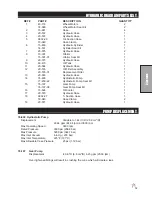
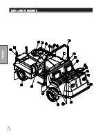
Page 18: ...16 Diagrams BODY FRAME DRAWING ...
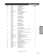
Page 20: ...18 Parts NOSE CONE DRAWING ...
Page 22: ...20 Parts NOSE CONE DRAWING ...
Page 24: ...22 Parts LINKAGE DRAWING ...
Page 26: ...24 Parts FRONT AXLE DRAWING ...
Page 28: ...26 Parts OIL AND FUEL TANK DRAWING ...
Page 30: ...28 Parts SEAT PANEL DRAWING ...
Page 32: ...30 Parts ENGINE AND PUMPS DRAWING ...
Page 34: ...32 Parts ENGINE AND PUMPS DRAWING ...
Page 36: ...34 Parts SPRAY PUMP DRAWING ...
Page 38: ...36 Parts REAR AXLE DRAWING ...
Page 40: ...38 Parts SPRAY TANK DRAWING ...
Page 42: ...40 Parts TURBO QUAD AGITATOR DRAWING ...
Page 44: ...42 Parts 15 301 ORBITOR DRAWING ...
Page 48: ...46 Parts 76 638 HYDROSTATIC PUMP DRAWING ...
Page 50: ...48 Parts 43 116 REAR WHEEL MOTOR DRAWING ...
Page 58: ...56 Accessories STAR COMMAND I II PLUMBING 15 818 75 Fitting O ring 15 817 50 Fitting O ring ...
Page 61: ...59 Accessories STAR COMMAND I WIRING 10 638 Fiberglass Cover 10 716 Dynajet Cover ...
Page 68: ...66 Accessories NOTES ...
Page 70: ...68 Accessories 17 580 20 HEAVY BOOM ...
Page 72: ...70 Accessories 17 580 20 BOOM DRAWING ...
Page 78: ...76 Accessories 17 585 18 HD BOOM DRAWING ...
Page 80: ...78 Accessories 17 585 18 HD BOOM DRAWING ...
Page 84: ...82 Accessories 17 601 15 HD BOOM DRAWING ...
Page 86: ...84 Accessories 17 601 15 HD BOOM DRAWING ...
Page 96: ...94 Accessories 30 010 ELECTRIC HOSE REEL DRAWING ...
Page 100: ...98 Accessories HOSE REEL MOUNT DRAWING ...
Page 102: ...100 Accessories 30 004 FOAM MARKER DRAWING WIRING DRAWING Spray Star 3180 Spray Star 2000 ...
Page 104: ...102 Accessories FOAMER NOZZLE MOUNT HOSE GUARD MOUNT DRAWING ...
Page 106: ...104 Accessories 14 291 FOAMER REPLACEMENT PARTS ...
Page 112: ...110 Accessories 15 620 CHEMICAL CLEAN LOAD PARTS DRAWING ...
Page 116: ...114 Reference NOTES ...


