16
Operation
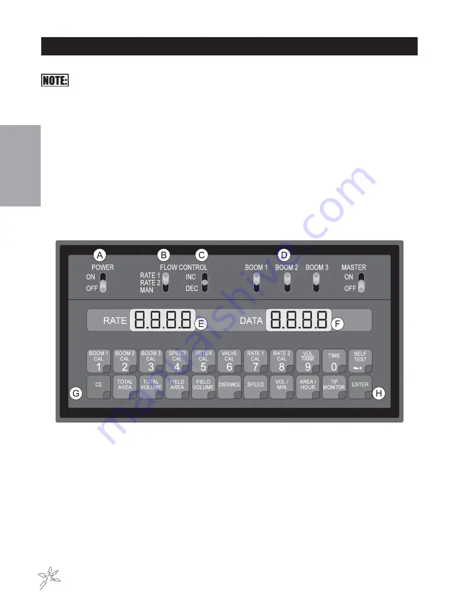
CONSOLE FEATURES
This Console (PGM F) requires selection of US (acres); SI (hectares) or TU (1,000 sq ft) area and
SP1 (wheel drive, etc).
A. POWER - Turns Console power OFF or ON. Turning Console OFF does not affect the data stored in
the computer.
B. Select manual or fully automatic control. This can automatically control two rates.
C. Manual override control provides capability for spot spraying.
D. Booms can be controlled individually, or all at once with MASTER ON/OFF Switch
E. Displays operating rate of application and flashing Tip Fault.
F. Displays function and calibration data.
G. CE - Use like you do CE (clear entry) key on a calculator. This key is also used to select an area
base measurement of US (acres), SI (Hectares) or TU (1,000 sq ft).
H. ENTER - Used only to enter the data into the Console.
Calibration Keys: (Top Row) Used to enter
Function Keys: (Bottom Row) Used to display data.
data into console to calibrate the system.
BOOM 1 CAL
Length of Boom 1
TOTAL AREA
Total Area Sprayed
BOOM 2 CAL
Length of Boom 2
FIELD AREA
Field Area Sprayed
BOOM 3 CAL
Length of Boom 3
FIELD VOLUME
Volume Applied to Field
SPEED CAL
Measured Off Drive Line(688)
DISTANCE
Distance Traveled
METER CAL
Flow Meter Calibration Number
SPEED
Speed of Vehicle
VALVE CAL
Control Valve Response Time
VOLUME/TANK
Volume Remaining in Carrier Tank
RATE 1 CAL
Target Application Rate
TIME
24 hour clock (military time)
RATE 2 CAL
Target Application Rate
TIP MONITOR
Use to Display Tip Faults
SELF TEST
Simulates Vehicle Speed
Summary of Contents for 3002
Page 28: ...26 Schematics WIRINGSCHEMATIC HYDRAULICSCHEMATIC ...
Page 45: ......

