background image

Super Star X-Treme

43-000-B

SN: 43057

March 2007

Product Support:

Hwy SS & Poplar Ave; Cameron WI 54822
1-800-891-9435      productsupport

@

smithco.com

Parts & Service

Summary of Contents for 43-000-B

Page 1: ...Super Star X Treme 43 000 B SN 43057 March 2007 Product Support Hwy SS Poplar Ave Cameron WI 54822 1 800 891 9435 productsupport smithco com Parts Service...

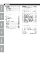
Page 2: ...223Adjustable Disc Edger 50 51 42 008 Sand Cultivator 52 53 42 340 Sand Cultivator w Spring Tine 54 55 42 341 Sand Cultivatore w Castor Wheels 56 57 42 010 Construction Leveling Blade 58 59 42 210 Gra...

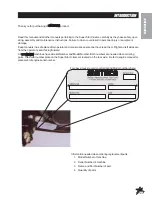
Page 3: ...y and maintenance instructions Failure to do so could result in personal injury or equipment damage Keep manuals in a safe place after operator and maintenance personnel have read them Right and left...

Page 4: ...After engine has started machine must not move If movement is evident the neutral mechanism is not adjusted correctly Shut engine off and readjust so the machine does not move when in neutral positio...

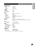
Page 5: ...ressure Alternator 16 amp WHEELS TIRE Three 22 X 11 10 0 Knobby Tires 5 psi 35 bar Front tire fluid filled to 80 lbs total 45 5 pints of windshield washer fluid or equivalent Speed Forward Speed 0 to...

Page 6: ...pressurized air to clean cartridge Pressurized air can damage cartridge 4 Reinstall cartridge plate and knob 5 Reassemble pre cleaner on cartridge 6 Replace cover and reattach clips to body REMOTEAIRC...

Page 7: ...lly which ever is first and change filter after the first 20 hours then at 100 hours then every 250 hours thereafter 3 The oil level should be 2 to 21 2 from top of tank when fluid is cold Do not over...

Page 8: ...over decrease charging Always remove grounded battery clamp first and replace it last Avoid hazards by 1 Filling batteries in well ventilated areas 2 Wear eye protection and rubber gloves 3 Avoid bre...

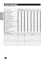
Page 9: ...oil filter after first 20 and first 100 hours Check the engine oil Check the hydraulic fluid level Check the tire pressure Check condition of hydraulic hoses and fittings Inspect and clean the machin...

Page 10: ...he engine cooling fins Check for unusual engine noises Check the hydraulic oil level Check hydraulic hoses and fittings for damage Check for fluid leaks Check the tire pressure 5 psi Check the Instrum...

Page 11: ...chine to operate at a proper speed while raking sand traps on golf courses This speed boss has been factory set at an aver age speed of 3 4 m p h 5 6 5 kph The Speed Boss will only limit the speed whi...

Page 12: ...sen the bolt A 3 With engine running adjust the ball bearing right or left in slot so ball bearing centers on the swash arm 4 Tighten all fasteners and test by using foot pedal linkage to see that the...

Page 13: ...e block that is through the throttle plate Do not let the throttle plate move to increase idle speed Tighten the screw 6 Test run to determine that there is no binding and that engine idle speed is 12...

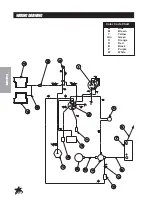
Page 14: ...12 Diagrams WIRINGDRAWING Color Code Chart Bl Blue Br Brown Y Yellow Grn Green O Orange R Red B Black P Purple W White...

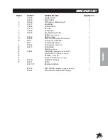
Page 15: ...Cable 1 9 42 252 Wire Circuit Breaker to Solenoid 1 10 8975 30Amp Circuit Breaker 1 8977 Circuit Breaker Boot 1 11 13 492 Solenoid B S 807829 1 12 22 017 Cable Black 1 13 Starter on engine 1 14 13 49...

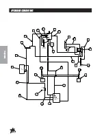
Page 16: ...14 Diagrams HYDRAULICDRAWING...

Page 17: ...13 615 Rear Wheel Motor 2 18 43 032 Hydraulic Hose 40 1 19 43 071 Hydraulic Hose 69 5 1 20 8832 27 3 4 Suction Hose 27 1 18 222 Hose Clamp 2 21 23 006 Oil Filter 1 23 031 Replacement Filter only 22 4...

Page 18: ...16 Parts MAINFRAMECOMMONDRAWING...

Page 19: ...up Holder 1 11 78 418 Valve Handle 2 12 42 772 Seat Panel 1 8803 17 Trim w Black Lace 1 13 14 518 Adjustable Low Back Seat 1 14 42 779 Seat Panel fiberglass 1 15 13 718 Steering Wheel 1 16 76 364 90 B...

Page 20: ...18 Parts FRONTFORKDRAWING...

Page 21: ...Woodruff Key 1 4 1 part of 76 238 1 16 18 350 90 Seal Lok Elbow 2 17 76 238 Wheel Motor 1 18 HB 12 13 650 Bolt 1 2 13 x 61 2 4 19 43 053 Front Fork 1 20 HNFL 12 13 Flange Whiz Lock Nut 1 2 13 4 22 20...

Page 22: ...20 Parts LINKAGEDRAWING...

Page 23: ...nsole fiberglass 1 11 42 471 Nose Cone fiberglass 1 12 42 790 Foot Pedal 1 HG 14 28 180 Grease Fitting 1 4 28 x 180 comes with 42 790 1 76 299 Pedal Pad Long 1 42 791 Pedal Pad Short 1 HB 516 18 150 B...

Page 24: ...22 Parts LINKAGEDRAWING...

Page 25: ...Joint 5 16 24 2 31 43 051 Speed Boss Arm 1 32 43 055 Engine Plate 1 33 42 779 Seat Panel 1 34 78 418 Levers 2 42 765 Decal Lift Controls 1 35 42 317 Light 1 42 317 01 Replacement Bulb 1 HSTP 14 20 10...

Page 26: ...24 Parts GASTANKDRAWING...

Page 27: ...th 42 006 1 8800 41 Fuel Hose 1 18 186 Hose Clamp 2 9 HB 12 13 500 Bolt 1 2 13 x 5 2 HNFL 12 13 Flange Whiz Lock Nut 1 2 13 2 10 42 015 Attachment Mount 1 11 42 273 Battery Box 1 12 HB 516 18 200 Bolt...

Page 28: ...26 Parts OILTANKDRAWING...

Page 29: ...4 Oil Tank Bracket 1 HB 516 18 225 Bolt 5 16 18 x 21 4 2 HNFL 516 18 Flange Whiz Lock Nut 5 16 18 2 9 42 015 Attachment Mount 1 10 HB 12 13 500 Bolt 1 2 13 x 5 2 HNFL 12 13 Flamge Whiz Lock Nut 1 2 13...

Page 30: ...28 Parts ENGINEDRAWING...

Page 31: ...38 Washer 3 8 1 HWL 38 Lock washer 3 8 1 HNTL 38 16 Lock Nut 3 8 16 1 17 43 054 Shift Arm 1 HRP 14 100 Roll Pin 1 4 100 1 18 11 103 Linkage Yoke 2 13 648 Cable 1 20 42 600 Muffler 1 42 601 Muffler Gue...

Page 32: ...30 Parts ENGINEDRAWING...

Page 33: ...1 4 Lock Washer 7 16 Coupler Half 4 1 Bore 1 HSSHS 716 14 075 Socket Head Set Screw 7 16 14 x 3 4 1 HSSHS 38 16 038 1 HKSQ 14 100 1 43 43 098 1 44 43 097 Socket Head Set Screw 3 8 16 x 3 8 Machine Key...

Page 34: ...32 Parts Torque To 120 ft lbs 156Nm REARAXLEDRAWING...

Page 35: ...lt 1 2 13 x 7 6 HNTL 12 13 Lock Nut 1 2 13 6 11 42 496 Right Caliper CW 1 12 11 100 Linkage Yoke 2 HCP 516 100 Clevis Pin 5 16 x 1 2 HP 18 100 Cotter Pin 1 8 x 1 2 13 HB 516 18 175 Bolt 5 16 18 x 13 4...

Page 36: ...34 Parts RAKELIFTDRAWING...

Page 37: ...t 1 2 13 x 5 4 HNFL 12 13 Flange Whiz Lock Nut 1 2 13 4 7 HCP 12 150 Clevis Pin 1 2 11 2 1 8 18 168 90 Elbow 2 9 42 015 Attachment Mount 2 10 13 357 Hydraulic Cylinder 1 HNJ 34 16 Jam Nut 3 4 16 1 11...

Page 38: ...36 Parts 13 729 2 BANKHYDRAULICVALVEDRAWING...

Page 39: ...acer 2 6 78 415 06 AType Spool HDS11 2 7 78 415 11 Positioner 2 8 78 415 08 Plug 2 9 78 415 09 Lever Group HDS11 2 10 78 415 10 Metric Socket Screw M5 x 8 x 45 4 11 78 415 12 Check ValveAssembly HDM12...

Page 40: ...38 Parts 76 238FRONTWHEELMOTORDRAWING 14 5CI...

Page 41: ...g Seal 5 9 13 032 31 Manifold 1 10 13 032 32 Commulator Assembly matched set 1 11 13 032 33 End Cover 1 12 76 238 01 Bolt 7 13 Commulator Seal matches with 10 1 14 76 238 02 Rotor Set matched set 1 15...

Page 42: ...40 Parts 13 615REARWHEELMOTOR 7 5C I DRAWING...

Page 43: ...Bearing 1 7 13 615 03 Drive Link 1 8 Ring Seal 5 9 13 032 31 Manifold 1 10 13 032 32 Commulator Assembly matched set 1 11 13 032 33 End Cover 1 12 13 615 01 Bolt 7 13 Commulator Seal matches with 10 1...

Page 44: ...42 Accessories 43 003 HYDRAULICSANDPLOWDRAWING HYDRAULICVALVEPLUMBINGDRAWING...

Page 45: ...HNTL 38 16 Lock Nut 3 8 16 2 14 HNJ 12 20 Jam Nu t 1 2 20 2 15 27 073 Lift Rod 2 16 27 017 Aluminum Sand Plow Blade 1 17 HB 38 16 100 Bolt 3 8 16 x 1 4 HNFL 38 16 Flange Whiz Lock Nut 3 8 16 4 18 13 1...

Page 46: ...44 Accessories 43 003 HYDRAULICSANDPLOWDRAWING HYDRAULICVALVEPLUMBINGDRAWING...

Page 47: ...towards the machine 9 Connect the 57 Hose Ref 31 to the inlet on the Single Bank Hydraulic Valve Ref 5 Connect the 75 Hose Ref 34 to the OUT port Next connect the 18 Hose Ref 27 to the fitting in the...

Page 48: ...46 Accessories 42 011 ABALUMINUMSANDPLOWDRAWING 42 011 SBSTEELSANDPLOWDRAWING...

Page 49: ...e hardware in Using hole closest to the blade will result in a shallow cut whereas using the hole furthest from the blade will result in a deeper cut The slot on the pusher bar is for fine tuned adjus...

Page 50: ...48 Accessories 42 13660 SANDPLOWDRAWING...

Page 51: ...hole closest to the blade will result in a shallow cut whereas using the hole furthest from the blade will result in a deeper cut The slot on the pusher bar is for fine tuned adjustment 2 Assemble th...

Page 52: ...50 Accessories 42 223ADJUSTABLEDISCEDGERDRAWING...

Page 53: ...the1 2 13 bolts washers and lock nuts Ref 4 to hold in place 2 Make sure the 1 2 disc flange Ref 9 is on the spindle shaft Ref 8 up to the shoulder Then place the disc Ref 10 onto the shaft curved tow...

Page 54: ...52 Accessories 42 008SANDCULTIVATORDRAWING...

Page 55: ...HCP 58 250 Clevis Pin 5 8 x 21 2 1 14 18 154 Rod End 1 42 008 Sand Cultivator all other parts reference only INSTALLATIONINSTRUCTIONS 1 Install valve handle with linkage 13 672 onto valve 2 Remove the...

Page 56: ...54 Accessories 42 340SANDCULTIVATORWITHSPRINGTINESDRAWING...

Page 57: ...100 Hex Bolt 5 16 18 x 1 12 3 42 122 Rake Spring 12 4 HNTL 38 16 Lock Nut 3 8 16 6 5 HW 38 Flat Washer 3 8 12 6 HNTL 516 18 Lock Nut 5 16 18 12 7 HB 38 16 100 Hex Bolt 3 8 16 x 1 6 8 HHP 18 Bridge Pi...

Page 58: ...56 Accessories 42 341FIELDSCARIFIERWITHTINES ANDCASTORWHEELSDRAWING...

Page 59: ...NTL 38 16 Lock Nut 3 8 16 10 11 HMB 34 14 Machine Bushing x 14GA 2 12 HW 38 Flat Washer 3 8 12 13 HNTL 516 18 Lock Nut 5 16 18 12 14 42 289 Right Castor Wheel Bracket 1 10 025 Flange Bushing Part of 4...

Page 60: ...58 Accessories 42 010CONSTRUCTIONLEVELINGBLADEDRAWING...

Page 61: ...is Pin 3 4 13 4 1 13 10 135 Hydraulic Cylinder 1 42 010 Construction Leveling Blade all other parts are reference only INSTALLATIONINSTRUCTIONS 1 Remove the cylinder mount Ref 10 from the machine 2 Bo...

Page 62: ...60 Accessories 42 210GRADERBLADEDRAWING BLADECLIPDRAWING...

Page 63: ...o be centered on the rear of the Seat Panel as illustrated Mark the hole locations on the Seat Panel Using an 11 32 drill located the holes at the four marks made previously The top two holes will be...

Page 64: ...62 Accessories 42 178INFIELDSCARIFIERWITHVERTICALBLADESDRAWING...

Page 65: ...1 2 13 2 9 42 204 Castor Fork 2 10 42 212 Castor Wheel Spacer 4 11 42 202 Tire and Wheel 2 42 202 01 Tire 9 x 3 5 x 4 Ply 2 42 202 02 Wheel 2 42 202 03 Cap 2 42 202 04 Bearing 2 42 202 05 Seal 2 12 42...

Page 66: ...64 Accessories 42 178SCARIFIERMOUNTINGDRAWING...

Page 67: ...e empty linkage port of the two bank valve on the machine 4 Slide the Scarifier under the machine lining up the hydraulic cylinder and the center of the attachment lift assembly 5 Extend hydraulic cyl...

Page 68: ...66 Accessories 42 179INFIELDSCARIFIERWITHCHISELBLADESDRAWING...

Page 69: ...1 2 13 2 9 42 204 Castor Fork 2 10 42 212 Castor Wheel Spacer 4 11 42 202 Tire and Wheel 2 42 202 01 Tire 9 x 3 5 x 4 Ply 2 42 202 02 Wheel 2 42 202 03 Cap 2 42 202 04 Bearing 2 42 202 05 Seal 2 12 42...

Page 70: ...68 Accessories 42 179SCARIFIERMOUNTINGDRAWING...

Page 71: ...e empty linkage port of the two bank valve on the machine 4 Slide the Scarifier under the machine lining up the hydraulic cylinder and the center of the attachment lift assembly 5 Extend hydraulic cyl...

Page 72: ...70 Accessories 42 285SCARIFIERWITHVERTICALBLADES...

Page 73: ...3 2 9 42 204 Castor Fork 2 10 42 212 Castor Wheel Spacer 4 11 42 202 Tire and Wheel 2 42 202 01 Tire 9 x 3 5 x 4 Ply 2 42 202 02 Wheel 2 42 202 03 Cap 4 42 202 04 Bearing 4 42 202 05 Seal 4 12 42 213...

Page 74: ...72 Accessories 42 285SCARIFIER WITHVERTICALBLADESMOUNTINGDRAWING...

Page 75: ...Ref 7 from the machine 3 Place the handle and linkage onto the empty linkage port of the two bank valve on the machine 4 Slide the Scarifier under the machine lining up the hydraulic cylinder and the...

Page 76: ...74 Accessories 42 02684 213CM STAINLESSSTEELTOURNAMENTRAKEDRAWING...

Page 77: ...Bridge Pin 1 8 1 12 HP 18 100 Cotter Pin 1 8 x 1 1 13 HB 14 20 175 Bolt 1 4 20 x 13 4 1 HNTL 14 20 Lock Nut 1 4 20 1 14 HSTPS 516 18 125 Stainless Steel Phillips Truss Head Screw 5 16 18 x 11 4 4 HWL...

Page 78: ...76 Accessories 42 02684 213CM STAINLESSSTEELTOURNAMENTRAKEDRAWING...

Page 79: ...e top strap Ref 16 to the inside and outside mounts using stainless steel truss head screw 5 16 18 x 1 Ref 1 Attach four finishing blades Ref 2 to the matting on the inside and outside mounts with the...

Page 80: ...78 Accessories 42 12872 183CM STAINLESSSTEELTOURNAMENTRAKEDRAWING...

Page 81: ...Pin 1 8 1 12 HP 18 100 Cotter Pin 1 8 x 1 1 13 HB 14 20 175 Bolt 1 4 20 x 13 4 1 HNTL 14 20 Lock Nut 1 4 20 1 14 HSTPS 516 18 125 Stainless Steel Phillips Truss Head Screw 5 16 18 x 11 4 4 HWL 516 Loc...

Page 82: ...80 Accessories 42 12872 183CM STAINLESSSTEELTOURNAMENTRAKEDRAWING...

Page 83: ...e top strap Ref 16 to the inside and outside mounts using stainless steel truss head screw 5 16 18 x 1 Ref 1 Attach four finishing blades Ref 2 to the matting on the inside and outside mounts with the...

Page 84: ...82 Accessories 13 438RAKEASSEMBLYWITHFINISHINGBLADESDRAWING...

Page 85: ...link Ref 18 Blades may be mounted with saw tooth up or down depending on the desired finish of the sand trap 6 Attach the rake hitch Ref 16 to trap rake hitch on the rear axle using a clevis pin and b...

Page 86: ...84 Accessories 13 684SANDRAKEBRUSHKITDRAWING HOLE LOCATION...

Page 87: ...Nuts 1 4 20 4 INSTALLATIONINSTRUCTIONS 1 Place the brush Ref 2 into the brush track Ref 1 Place the brush channel Ref 3 between the brush track and the mounting brackets Now bolt the mounting brackets...

Page 88: ...86 Accessories 13 298FANRAKEATTACHMENTDRAWING 13 319FANRAKEKIT...

Page 89: ...the hitch using the clevis pin and the bridge pin Ref 7 4 Hook the chains from the frame to the hooks on the rake lift 13 319FANRAKEKITPARTSLIST REF PART DESCRIPTION QUANTITY 1 13 326 Left Holder 1 2...

Page 90: ...88 Accessories 26 007PROFESSIONALINFIELDFINISHERDRAWING 42 185DRAGMATKITDRAWING...

Page 91: ...is pin Ref 4 and bridge pin Ref 11 4 Hook chains from finisher to rake lift arms 5 NOTE When assembled properly rake will angle down from front to back If front of finisher is not higher than the back...

Page 92: ...90 Accessories 43 002 FLEXACTIONFIELDFINISHERWITH BRUSHDRAWING...

Page 93: ...2 HB 14 20 075 Bolt 1 4 20 x 3 4 8 HNFL 14 20 Flange Whiz Lock Nut 1 4 20 8 13 13 688 Brush Channel 1 14 13 683 Brush Track 1 15 13 682 Brush 77 x 11 1 16 26 041 Rasp Flail 32 17 11 040 Spacer 3 4 2 1...

Page 94: ...92 Accessories 43 002 FLEXACTIONFIELDFINISHERWITH BRUSHDRAWING...

Page 95: ...6 x 1 bolt and 3 8 16 center lock nut Loose fit is required Do not over tighten 7 Flip assembly over so knobby sides of flails are now facing down Install hitch Ref 25 to frame with clevis pin Ref 3 a...

Page 96: ...94 Accessories 26 008FLEXACTIONFIELDFINISHERDRAWING...

Page 97: ...g Bar 1 8 26 047 Leveler Bar 1 9 21 260 3 8 Chain Clevis 2 10 26 115 Mesh Finisher 1 11 HMB 58 14 Machine Bushing 5 8 x 14GA 10 12 11 040 Spacer 3 4 2 13 26 041 Rasp Flail 32 14 HW 58 Washer 5 8 32 15...

Page 98: ...96 Accessories 26 008FLEXACTIONFIELDFINISHERDRAWING...

Page 99: ...r bar chain on to pin and secure in place with bridge pin Use last bridge pin and clevis pin to hitch field finisher to your machine 9 Add extension arms Ref 20 to rake lift Super Star use the center...

Page 100: ...98 Accessories 43 043 FINISHINGBRUSHKITDRAWING HOLELOCATION...

Page 101: ...our unit it will not be used with the brush 2 Place the brush Ref 1 into the brush track Ref 2 Place the brush channel Ref 4 between the brush track and the mounting brackets Ref 5 Now bolt the mounti...

Page 102: ...100 Accessories 42 582 GREEN STAR RBS SPIKER SET 3 DRAWING...

Page 103: ...ons The unit comes pre adjusted for most models When in stalling spiker system use lower mounting holes on hitch Tire pressure should be 4 psi in the front and 7 psi in the rear tire for best traction...

Page 104: ...102 Accessories 42 586GREENSTARRBSMAINFRAMEDRAWING...

Page 105: ...hree Point Hitch 1 10 42 566 Lift Strap 4 11 HMB 12 14 Machine Bushing 1 2 x 14GA 1 HP 18 100 Cotter Pin 1 8 x 1 1 12 HMB 100 14 Machine Bushing 1 x 14GA 1 13 42 539 Lynch Pin5 16 4 14 42 536 Spring 6...

Page 106: ...104 Reference NOTES...

Page 107: ...60 Manual Plow 42 130 Mild Steel Tournament Rake 84 42 460 40 AdjustableAngle Plow 42 132 Mild Steel Tournament Rake 72 42 490 60 AdjustableAngle Plow 42 391 72 Multi Brush Rake 43 130 Weed Cultivato...

Page 108: ...492932 SEALKITS 43 127 Variable Pump 13 615 Wheel Motor 14 080 Seal Kit 76 238 Wheel Motor 14 080 Seal Kit 13 729 2 Bank Valve 78 415 03 Seal Kit 10 135 Hydraulic Cylinder Attachment Lift Cylinder 13...

Page 109: ...you need help locating an Authorized Smithco Distributor or if you have questions regarding your warranty rights or responsibilities you may contact us at Smithco Product Support Department 200 W Pop...

Page 110: ...ty gives you specific legal rights and you may also have other rights which vary from state to state THERE ARE NO OTHER EXPRESS WARRANTIES OTHER THAN THOSE SET FORTH ABOVE ALL IMPLIED WARRANTIES OF ME...

Reviews: