45
Accessories
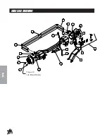
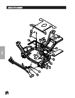
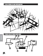
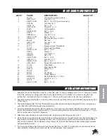
43-003 HYDRAULIC SAND PLOW INSTRUCTIONS
1.
Assemble Pusher Bars (Ref # 22 and 25) to Plow Blade (Ref # 16) using one
3
/
8
-16 x 1 Bolt (Ref # 19) and
one
3
/
8
-16 x 3 Bolt (Ref #21) per Pusher Bar. There are 2 holes to bolt (Ref # 19) hardware in. Using hole closest
to the blade will result in a shallow cut, whereas using the hole furthest from the blade will result in a deeper cut.
The slot on the pusher bar is for a more fine tuned adjustment.
2.
Assemble the Lift Assembly (Ref # 10) to the Main Frame using the two studs that are under the frame and
below the front of the console.
3.
Place Cylinder Lift (Ref # 26) into the tube on Lift Assembly (Ref # 10) with the tab pointing up hold with a
3
/
8
-16 x
2 Bolt (Ref # 13), assemble the Valve Mount (Ref # 6) onto this bolt on the outside of the tube and secure both
with one
3
/
8
-16 Nut. Using a
3
/
8
-16 x 2 Bolt mount the Hydraulic Cylinder (Ref # 12) to the Lift Assembly and
secure with one
3
/
8
-16 Nut. Connect the other end of the Hydraulic Cylinder to the Cylinder Lift using ½ x 1½
Clevis Pin (Ref # 23) and
1
/
8
x 1 Cotter Pin (Ref #11).
4.
Thread one ½ - 20 Jam Nut (Ref # 14) onto each Lift Rod (Ref # 15) followed by the Rod Ends (Ref # 9). Adjust to
equal lengths. Bolt Lift Rods to Lift Arms on Lift Assembly (Ref # 10) with Rod Ends to the outside. Bolt from
outside with the ½” Machine Bushing (Ref # 8) between Rod End and Lift Arm and secure with ½ -13 Lock Nut.
5.
Slide the Plow/Pusher Bar Assembly under machine and connect to machine. Secure using ½ x 1½ Clevis Pins
(Ref # 23) and
1
/
8
" Bridge Pins (Ref # 24).
6.
To connect Lift Rods (Ref # 15) to Pusher Bars start by lifting up the Plow Blade. Using one
3
/
8
-16 x 3 Bolt (Ref #
20) and two
3
/
8
" Washers assembly the Lift Rods to the Right (Ref #22) and Left (Ref # 25) Pusher Bars using
the bottom hole in the Lift Rods as illustrated. Secure each with one
3
/
8
-16 Lock Nut.
7.
To fine tune the height of the blade off ground; turn the Rod Ends (Ref # 9) on the Lift Rods (Ref # 15). Turning
the Rod Ends counter-clockwise will increase down pressure. Turning them clockwise will decrease down
pressure.
8.
Thread two of the 45° Elbow fittings (Ref # 2) into the Single Bank Valve (Ref # 5), one each in the A port, B port.
Thread two of the 90° Elbow fittings (Ref # 29) into the Single Bank Valve IN port and OUT port. Thread the
remaining two 45° (Ref # 2) Elbow fittings into the ports on the Hydraulic Cylinder (Ref # 12). Make sure the
fittings on the Hydraulic Cylinder are pointing towards the machine.
9.
Connect the 57½" Hose (Ref # 31) to the inlet on the Single Bank Hydraulic Valve (Ref #5). Connect the 75"
Hose (Ref # 34) to the OUT port. Next connect the 18" Hose (Ref # 27) to the fitting in the B port and connect the
20" Hose (Ref # 28) to the fitting in the A port.
10.
Mount the Single Bank Hydraulic Valve (Ref # 5) to the Valve Mount (Ref # 6) as illustrated using the two ¼ - 20 x 2
Bolts (Ref # 4). Secure with the two ¼ - 20 Flange Whiz-Lock Nuts. Connect the Straight Handle Kit (Ref # 3) to
the Valve. Reference Single Bank Hydraulic Valve Drawing on page 6 for a detailed view of the Valve. The Single
Bank Valve is used in some other applications, therefore the handle housing may need to be reversed. Remove
the two screws holding the housing assembly onto the valve body, turn it over and reinstall the screws. The
handle must be pointing upward (reference drawing on page 44) when the valve is sitting on a table.
11.
Route the 18" Hose (Ref # 29) from the B port on the Single Bank Hydraulic Valve (Ref # 5) to the rear port on the
Hydraulic Cylinder. Route the 20" Hose (Ref # 30) from the A port on the Single Bank Hydraulic Valve to the front
port on the Cylinder.
12.
Disconnect the negative (-) ground battery cable from the battery. Place a drain pan under the valve on the
machine. ENGINE MUST BE COOL BEFORE DISCONNECTING THE HOSES.
13.
Disconnect the hose from the T port on the 2 Bank Valve (Ref # 32) and the top port on the Oil Cooler. Discard
this hose, it will not be used. Connect the 75" Hose (Ref # 34) from the T port on the Single Bank Valve to the top
port on the Oil Cooler. This hose may be a bit long on the Gasoline Models so you may have to loop the hose
around the back of the pump to use up some hose. Connect the 57½" Hose (Ref # 31) from the P port of the
Single Bank Valve to the T port of the 2 Bank Valve. Tie up Hoses using
5
/
8
Loom Clamp (Ref # 28). Route the
57½" & 75" Hoses under the body and along the frame avoiding any pinch points. Fasten to the frame using the
14½" Nylon Ties.
14.
Reconnect the negative (-) ground battery cable to battery.
15.
Make sure that everything is clear of the machine. Start the machine, work the valve so that the plow will both
raise and lower. Also, do this with both the attachment lift and the rake lift. Work the lift a number of times until all
air works out of the plow circuit and the cylinder works smoothly. At this time look for hydraulic leaks. If there are
leaks, turn engine off and repair, start up and check again.
16.
Check the hydraulic oil level. The level should be 2” to 2½” below the top of the tank. If more is
needed, use SAE 10W-40 API service SG motor oil.
Summary of Contents for 43-000-B
Page 16: ...14 Diagrams HYDRAULICDRAWING...
Page 18: ...16 Parts MAINFRAMECOMMONDRAWING...
Page 20: ...18 Parts FRONTFORKDRAWING...
Page 22: ...20 Parts LINKAGEDRAWING...
Page 24: ...22 Parts LINKAGEDRAWING...
Page 26: ...24 Parts GASTANKDRAWING...
Page 28: ...26 Parts OILTANKDRAWING...
Page 30: ...28 Parts ENGINEDRAWING...
Page 32: ...30 Parts ENGINEDRAWING...
Page 34: ...32 Parts Torque To 120 ft lbs 156Nm REARAXLEDRAWING...
Page 36: ...34 Parts RAKELIFTDRAWING...
Page 38: ...36 Parts 13 729 2 BANKHYDRAULICVALVEDRAWING...
Page 40: ...38 Parts 76 238FRONTWHEELMOTORDRAWING 14 5CI...
Page 42: ...40 Parts 13 615REARWHEELMOTOR 7 5C I DRAWING...
Page 44: ...42 Accessories 43 003 HYDRAULICSANDPLOWDRAWING HYDRAULICVALVEPLUMBINGDRAWING...
Page 46: ...44 Accessories 43 003 HYDRAULICSANDPLOWDRAWING HYDRAULICVALVEPLUMBINGDRAWING...
Page 48: ...46 Accessories 42 011 ABALUMINUMSANDPLOWDRAWING 42 011 SBSTEELSANDPLOWDRAWING...
Page 50: ...48 Accessories 42 13660 SANDPLOWDRAWING...
Page 52: ...50 Accessories 42 223ADJUSTABLEDISCEDGERDRAWING...
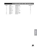
Page 54: ...52 Accessories 42 008SANDCULTIVATORDRAWING...
Page 56: ...54 Accessories 42 340SANDCULTIVATORWITHSPRINGTINESDRAWING...
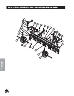
Page 58: ...56 Accessories 42 341FIELDSCARIFIERWITHTINES ANDCASTORWHEELSDRAWING...
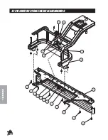
Page 60: ...58 Accessories 42 010CONSTRUCTIONLEVELINGBLADEDRAWING...
Page 62: ...60 Accessories 42 210GRADERBLADEDRAWING BLADECLIPDRAWING...
Page 64: ...62 Accessories 42 178INFIELDSCARIFIERWITHVERTICALBLADESDRAWING...
Page 66: ...64 Accessories 42 178SCARIFIERMOUNTINGDRAWING...
Page 68: ...66 Accessories 42 179INFIELDSCARIFIERWITHCHISELBLADESDRAWING...
Page 70: ...68 Accessories 42 179SCARIFIERMOUNTINGDRAWING...
Page 72: ...70 Accessories 42 285SCARIFIERWITHVERTICALBLADES...
Page 74: ...72 Accessories 42 285SCARIFIER WITHVERTICALBLADESMOUNTINGDRAWING...
Page 76: ...74 Accessories 42 02684 213CM STAINLESSSTEELTOURNAMENTRAKEDRAWING...
Page 78: ...76 Accessories 42 02684 213CM STAINLESSSTEELTOURNAMENTRAKEDRAWING...
Page 80: ...78 Accessories 42 12872 183CM STAINLESSSTEELTOURNAMENTRAKEDRAWING...
Page 82: ...80 Accessories 42 12872 183CM STAINLESSSTEELTOURNAMENTRAKEDRAWING...
Page 84: ...82 Accessories 13 438RAKEASSEMBLYWITHFINISHINGBLADESDRAWING...
Page 86: ...84 Accessories 13 684SANDRAKEBRUSHKITDRAWING HOLE LOCATION...
Page 88: ...86 Accessories 13 298FANRAKEATTACHMENTDRAWING 13 319FANRAKEKIT...
Page 90: ...88 Accessories 26 007PROFESSIONALINFIELDFINISHERDRAWING 42 185DRAGMATKITDRAWING...
Page 92: ...90 Accessories 43 002 FLEXACTIONFIELDFINISHERWITH BRUSHDRAWING...
Page 94: ...92 Accessories 43 002 FLEXACTIONFIELDFINISHERWITH BRUSHDRAWING...
Page 96: ...94 Accessories 26 008FLEXACTIONFIELDFINISHERDRAWING...
Page 98: ...96 Accessories 26 008FLEXACTIONFIELDFINISHERDRAWING...
Page 100: ...98 Accessories 43 043 FINISHINGBRUSHKITDRAWING HOLELOCATION...
Page 102: ...100 Accessories 42 582 GREEN STAR RBS SPIKER SET 3 DRAWING...
Page 104: ...102 Accessories 42 586GREENSTARRBSMAINFRAMEDRAWING...
Page 106: ...104 Reference NOTES...


