background image

13

Introduction

PARTS MANUALS  AVAILABLE ONLINE AT smithco.com

OPERATING INSTRUCTIONS 

(CONTINUED)

SPRAYER VALVE SETTINGS AND SPRAY TANK AGITATION

The gate valve on the suction side of the pump, between the tank and the pump must be open before pump is
engaged. Close this valve only when necessary to clean the filter with spray material in the spray tank.

There is one manual flow control valves on the discharge side of the spray system. 

This valve controls the agita-

tor. This valve may be opened as much as necessary to provide hydraulic agitation through the quadrajet agitator
in the tank bottom. This valve may be partially closed to prevent or reduce foam buildup from the spray materials
inside the tank. When the liquid level in the spray tank reaches a certain level (usually 1-25 gallons (3.8-95 Li-
ters) depending on terrain and  other conditions) it may be necessary to close the valve in the agitator line in
order to prevent loss of suction prime.

If your Spray Star is fitted with a hose reel, there is a second ball valve on the discharge system to supply mate-
rial to the hose reel.

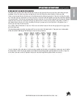
The Quadrajet agitation system operates with four venturi jets in the tank bottom. These jets have replaceable
orifice discs which discharge the following amounts of spay material.

Input to

Input to

Agitator

Agitator

Agitator

Agitator

Nozzle

Agitator

Agitator

Pressure Pressure

Output

Output

Diameter

in gpm

in L/min

in psi

in bar

in gpm

in  L/min

1

/

8

"

1.9

7.2

25

1.7

6.3

23.8

1

/

8

"

2.7

10.2

50

3.4

10.0

37.9

1

/

8

"

3.8

14.4

100

6.9

15.0

56.8

5

/

32

"

2.8

10.6

25

1.7

7.6

28.8

5

/

32

"

4.2

15.9

50

3.4

12.2

46.2

5

/

32

"

5.5

20.8

100

6.9

17.5

66.2

3

/

16

"

3.6

13.6

25

1.7

9.1

34.4

3

/

16

"

5.6

21.2

50

33.4

14.3

54.1

3

/

16

"

7.9

29.9

100

6.9

18.7

70.8

You can change orifice disc sizes to enhance spray system performance. Smaller discs reduce amount of agita-
tion (desirable in some foaming materials) and make more dischargeable liquid available for nozzles. Larger (or
none) discs increase amount of agitation and make less dischargeable liquid available for nozzles.

Summary of Contents for 440 System

Page 1: ...Spray Star 1762 440 System March 2014 Product Support Hwy SS Poplar Ave Cameron WI 54822 1 800 891 9435 productsupport smithco com Operator s ...

Page 2: ...nsole Setup 21 Console Field Test 22 Spray Operation 22 23 Schematics 24 25 Hydraulic Schematic 24 Wiring Schematic 25 Spraying Procedure 26 32 Spraying Introduction 26 Turf Management 26 Hose Handgun Spraying 27 Nozzles 27 28 Calibration Introduction 29 The Nozzle Chart Method of Calibration 30 31 The 128 Method of Boom Sprayer Calibration 31 32 Nozzle Charts 33 38 Nozzle Performance Chart 1 33 N...

Page 3: ...ting assembly and maintenance instructions Failure to do so could result in personal injury or equipment damage Keep manuals in a safe place after operator and maintenance personnel have read them Right and left sides are from the operator s seat facing forward All machines have a Serial Number and Model Number Both numbers are needed when ordering parts The serial number plate on the Spray Star i...

Page 4: ...Release Hydraulic Oil Level Choke Open Choke Closed Hand Throttle Hour Meter Hour Meter Fuse Glow Plug Glow Plug Off Glow Plug On RPM Gasoline Diesel Water Temperature Temperature Light Engine Oil Engine Stop Engine Start Engine Run No Electrical Power Electrical Power Read Operator s Manual ...

Page 5: ...MBOLS No Smoking Moving Parts Manual Operation Pinch Point Step Hot Surface Hydraulic Fluid Penetration Lift Arm Tractor Engage Disengage PTO Ground Speed Fast Slow H High L Low F Forward R Reverse N Neutral Warning Danger Caution Up Raise Down Lower Up Down Arrow ...

Page 6: ...ves and set park brake before starting the engine 12 Never use your hands to search for oil leaks Hydraulic fluid under pressure can penetrate the skin and cause serious injury 13 This machine demands your attention To prevent loss of control or tipping of the vehicle A Use extra caution in backing up the vehicle Ensure area is clear B Do not stop or start suddenly on any slope C Reduce speed on s...

Page 7: ...Check hoses for weak or worn condition before each use Make certain that all connections are tight and secure 11 Do not operate unit with leaks frayed kinked hoses or tubing Repair or replace immediately 12 Use only pipe hose and fittings rated for maximum pressure or pressure at which pressure relief valve is set at When replacing pipe hose or fittings use new product 13 Do not operate a gasoline...

Page 8: ...h 0 5 kph 2nd gear 2 6 m p h 3 10 kph Transport Speed 3rd gear 4 10 m p h 6 16 kph Reverse Speed 0 3 m p h 0 5 kph BATTERY Automotive type 24F 12 volt BCI Group Size 24 Cold Cranking Amps 575 minimum Ground Terminal Polarity Negative Maximum Length 10 25 26 cm Maximum Width 6 88 17 cm Maximum Height 10 25 cm FLUID CAPACITY Crankcase Oil 2 1 quart 2 liters with filter Fuel 6 gallon 22 7 liters Hydr...

Page 9: ...ing mechanism Ref C Tighten nut to 30 40 ft lb 41 54 Nm Do not over tighten 6 Install the seat with the stud going through the engine cover and the flat washers lock washers and nuts Use the front set of holes for shorter drivers and use the back set of holes for taller drivers 7 Be sure battery automotive type 24F 12 volt 575 cold cranking AMPS minimum 10 25 260 mm long x 6 88 175 mm wide x 10 25...

Page 10: ...e four bolts used to hold the tank in place 17 Read operating instructions before starting Never allow pump to run dry The valve on the suction side of the pump between the pump and tank must be fully open whenever the pump is operated DAILYCHECKLIST 1 Check park brake adjustment Adjust as required 2 Check engine oil level Add as needed DO NOT OVERFILL 3 Tire pressure should be 20 psi 1 4 bar fron...

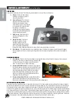
Page 11: ... spray pump on by pushing on the top and off by pushing on the bottom H Left Boom Switch This rocker switch lifts and lowers the left boom I Right Boom Switch This rocker switch lifts and lowers the right boom J Clutch Pedal Located to the left side on the floorboard Must be pressed down to disengage the clutch and activate the interlock switch K Brake Pedal Located in the middle of the floorboard...

Page 12: ...ten turn knob clock wise To loosen turn counter clockwise G Foamer ON OFF Switch Located to the right of the control panel Used to turn on and off the foam marker Also used to designate which boom is to be used to dispense foam With lever pointing toward the seat foam will dispense from right boom and with lever pointing forward foam will dispense from the left boom H Foamer Adjustment Knob Locate...

Page 13: ...ral 5 The ignition switch is located to the right of the steering column Insert the key A and turn clockwise until the engine starts C Release the key and it will return to the run position B Use the choke and hand throttle as necessary 6 Allow engine to idle and warm up before selecting direction of travel 7 Make sure the park brake is disengaged STOPPINGTHEENGINE If the engine has been running u...

Page 14: ...age the clutch to begin moving 4 Push the foot accelerator fully to the floor 5 While the foot accelerator is fully depressed begin moving the Ground Speed Control lever towards slow until the correct operating speed is attained 6 The desired speed will be maintained as long as the foot accelerator is fully depressed 7 Vehicle will return to the established ground speed whenever the foot accelerat...

Page 15: ...der to prevent loss of suction prime If your Spray Star is fitted with a hose reel there is a second ball valve on the discharge system to supply mate rial to the hose reel The Quadrajet agitation system operates with four venturi jets in the tank bottom These jets have replaceable orifice discs which discharge the following amounts of spay material Input to Input to Agitator Agitator Agitator Agi...

Page 16: ...a calculator This key is also used to select an area base measurement of US acres SI Hectares or TU 1 000 sq ft H ENTER Used only to enter the data into the Console DATA MENU Calibration Keys Top Row Used to enter Function Keys Bottom Row Used to display data data into console to calibrate the system BOOM 1 CAL Length of Boom 1 TOTAL AREA Total Area Sprayed BOOM 2 CAL Length of Boom 2 FIELD AREA F...

Page 17: ...ach boom in inches centimeters by multiplying the number of tips times the spacing Write these boom widths down for future reference when programming the Console computer The Console is capable of controlling up to three 3 booms CALCULATING SPEEDCAL 1 Enter Speed Cal in key of 114 2 Place Master and Boom 1 switches to on 3 Enter 0 in key 4 Drive 1 mile Do not use vehicle odometer to determine dist...

Page 18: ...o refine this number See definitions below Valve Backlash Controls the time of the first correction pulse after a change in correction direction is detected Incr to Decr or Decr to Incr Range 1 to 9 1 Short Pulse 9 Long Pulse Valve Speed Digit Controls the Speed of the Control Valve motor Running the Control Valve too fast will cause the system to oscillate Range 1 to 9 1 slow 9 Fast Brake Point D...

Page 19: ...y Steps the DATA display from US acres to SI b Depressing momentarily Steps the DATA display from SI Hectares to TU c Depressing momentarily Steps the DATA display from TU 1000 sq ft to US 2 Selecting US SI or TU a To select US SI or TU step until the desired code is displayed in DATA display b Momentarily depress the DATA display will now display SP1 3 Displaying SP1 or SP2 a Depressing momentari...

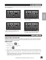
Page 20: ... of the system 13 Enter the estimated total Volume in Tank when you start spraying in key labeled Each time the tank is refilled this number must be reentered 14 Enter the TIME of day in the key labeled This is a 24 hour clock Therefore all time after 12 59 pm add 12 hours Thus 8 30 am is entered as 8 30 but 1 30 pm is entered as 13 30 in the keyboard OTHERDISPLAYFEATURES 1 To display TOTALAREA co...

Page 21: ...ions will be alternately displayed SELFTESTFEATURE SELF TEST allows speed simulation for testing the system while the vehicle is not moving Enter the simulated operating speed in the key labeled If 6 MPH 10km h is desired enter 6 0 10 0 Verify speed by de pressing key labeled SPEED The SELF TEST speed will clear itself when motion of vehicle is detected by the Speed Sensor A SPEED CAL Value of 900...

Page 22: ...lay time will appear b Enter new delay time 0 to 200 days using the same procedure as that for entering other data In the event of console power loss the power down delay time will default to 10 days CONSOLEALARMFEATURE Console alarm sounds if application rate is 30 or more away from target application rate for 5 seconds ALARMMENU Depress for 5 seconds until DATA display shows A on Depressing mome...

Page 23: ... than 30 seconds INITIALCONSOLESETUP 1 Fill tank with water only If positive displacement type pump is used fully open pressure relief valve PRV Open gate valve between the tank and pump 2 Place MASTER On Off to On and Boom On Off switches to Off 3 Place MAN RATE 1 RATE 2 switch to MAN 4 Place POWER On Off switch to On 5 Verify correct boom widths speed calibration meter calibration valve calibrat...

Page 24: ...ll strainer c Chemical in soluble packs are place into the fillwell strainer basket and dissolved by adding water through the basket The balance of the water required for the spray operation is added to the tank through the fillwell strainer using the air gap filler This will wash any undissolved chemical into the tank 5 Transport to sprayer site with and agitator operating 6 Set Engine speed betw...

Page 25: ... Replace screen and bowl taking care to position o ring or gasket properly Hand tighten 6 Remove and clean Flow Meter turbine and inlet hub Clean off all metal filings and wettable powders which have hardened on the plastic and metal parts Check the inlet hub and turbine assembly for worn or damaged turbine blades and bearings Flush Flow Meter with clear water and drain MANUALHOSEREEL Located at t...

Page 26: ...24 Schemat PARTS MANUALS AVAILABLE ONLINE AT smithco com HYDRAULICSCHEMATIC ...

Page 27: ...25 Schematics PARTS MANUALS AVAILABLE ONLINE AT smithco com WIRINGSCHEMATIC ...

Page 28: ...have to be applied so that they get into the soil below the plant leaves This is called soil appli cation In order to do this they are best applied with a large volume of water They are often then watered in using the irrigation system This type of chemical material includes systemic chemicals and chemicals designed to destroy pests which live in the thatch and the soil Other materials must be app...

Page 29: ...egulates the flow of liquid Obviously the larger the opening the greater the rate of flow volume Volume is expressed in Gallons Per Minute gpm or Liters Per Minute lpm Do not confuse the term volume with application rate which will be covered later As pressure increases the flow volume in a given nozzle also increases For example an average size nozzle which discharges 0 52 gpm 1 4 lpm at 30 psi 2...

Page 30: ...jet Nozzles TF VS4 and larger do not require screens SPACING Turf spray nozzles are normally 20 51 cm apart Some cases 40 101 cm depending on the type of spray boom and type of area to be sprayed Very fine level areas golf greens and tees bowling lawns tennis courts etc may be sprayed with nozzles spaced every 10 25 cm BOOM HEIGHT Height is very important in permitting spray nozzles to develop the...

Page 31: ...We have covered the different types of spray patterns of various nozzles and made our selection of type accord ingly We now have to choose a size which will provide the correct application rate Sizes are available for all requirements Consult the nozzle chart in this manual for your nozzle type in order to select the correct size TRAVELSPEED Increased travel speed decreases the application rate gp...

Page 32: ... be sprayed at 41 2 to 6 mph 7 10 kph The vehicle which carries or tows the sprayer should be equipped with a precise low speed speedometer If it is not exact ground speed at a given engine speed must be determined by timing the travel of the sprayer over a measured distance 4 Determine Nozzle Size Refer to the appropriate nozzle chart in the back of this manual for your nozzle TYPE the type of no...

Page 33: ...To convert any of the Gallon Per Acre rates to Imperial Gallons per acre Imp gpa multiply by 0 83 To convert any of the Liter Per Hectare rates to Imperial Gallons Per Hectare Imp GPH multiply by 0 22 8 Checking the Actual Application Rate After the combination of ground speed nozzle size and operating pressure has been selected the sprayer should be operated with water only to determine if the ta...

Page 34: ...lower than the intended rate adjustments must be made 7 Minor adjustments in application rate may be made by increasing or decreasing the spraying pressure Lowering spraying pressure decreases application rate Increasing spraying pressure increases application rate This procedure normally does not apply to spray systems controlled by an Electronic Spray Control System which governs flow rate 8 Adj...

Page 35: ...0 0 49 21 0 26 0 30 0 36 0 16 6 21 0 24 0 29 0 13 9 17 3 19 8 24 0 11 9 14 9 17 0 21 0 0 98 1 20 1 40 1 70 0 64 0 80 0 91 1 10 0 48 0 60 0 68 0 84 0 38 0 48 0 55 0 67 Brown XR8005 DG8005 20 30 40 60 0 35 0 43 0 50 0 61 26 0 32 0 37 0 45 0 21 0 26 0 30 0 36 0 17 3 21 0 25 0 30 0 14 9 18 2 21 0 26 0 1 20 1 50 1 70 2 10 0 80 0 98 1 10 1 40 0 60 0 73 0 85 1 00 0 48 0 59 0 68 0 83 Gray XR8006 20 30 40 ...

Page 36: ...Red XR8004 DG8004 1 5 2 0 3 0 4 0 1 12 1 29 1 58 1 82 336 387 474 546 269 310 379 437 224 258 316 364 192 221 271 312 Brown XR8005 DG8005 1 5 2 0 3 0 4 0 1 39 1 61 1 97 2 27 417 483 591 681 334 386 473 545 278 322 394 454 238 276 338 389 Gray XR8006 1 5 2 0 3 0 4 0 1 68 1 94 2 37 2 74 504 582 711 822 403 466 569 658 336 388 474 548 288 333 406 470 White XR8008 1 5 2 0 3 0 4 0 2 23 2 58 3 16 3 65 6...

Page 37: ...14 1 17 1 12 1 14 6 48 59 Blue TF VS5 20 30 0 71 0 87 26 0 32 0 21 0 26 0 17 6 22 0 15 1 18 5 60 74 Green TF VS7 5 20 30 1 06 1 30 39 0 48 0 31 0 39 0 26 0 32 0 22 0 28 0 90 1 11 Black TF VS10 20 30 1 41 1 73 52 0 64 0 42 0 51 0 35 0 43 0 30 0 37 0 1 20 1 47 Nozzle Type Spacing Calibration Color Size Pressure psi Nozzle Capacity Gal Min Application Rate GPA Speed MPH Application Rate GPT Speed MPH...

Page 38: ...23 2 57 335 386 223 257 167 193 112 129 Blue TF VP5 1 5 2 0 2 79 3 22 419 483 279 322 209 242 167 193 Green TF VP7 5 1 5 2 0 4 19 4 83 629 726 419 484 314 363 251 290 Black TF VP10 1 5 2 0 5 58 6 45 837 968 558 645 419 484 335 387 Nozzle Capacity l min Application Rate l ha Speed km h Application Rate GPT Speed MPH Turbo FloodJet 40 inch 100cm Liters Per Hectare Nozzle Type Spacing Calibration Col...

Page 39: ... 30 33 1 1 1 2 1 4 1 5 80 88 1 0 1 1 64 71 82 91 53 59 68 76 White 1 4TTJ08 VS 25 30 40 50 63 69 80 89 62 68 79 88 47 41 59 66 37 41 48 53 31 34 40 44 1 4 1 6 1 8 2 0 1 1 1 2 1 4 1 5 86 94 1 1 1 2 71 78 91 1 0 L Blue 1 4TTJ1 0 VS 25 30 40 50 79 87 1 00 1 12 78 86 99 111 59 65 74 83 47 52 59 67 39 43 50 55 1 8 2 0 2 3 2 5 1 3 1 5 1 7 1 9 1 1 1 2 1 4 1 5 90 99 1 1 1 3 L Green 1 4TTJ1 5 VS 25 30 40 5...

Page 40: ...1 5 2 0 3 0 1 37 1 68 1 94 2 37 206 252 291 356 137 168 194 237 103 126 146 178 82 2 101 116 142 White 1 4TTJ08 VP 1 0 1 5 2 0 3 0 1 82 2 23 2 57 3 15 273 335 385 473 182 223 257 315 137 167 193 236 109 134 154 189 L Blue 1 4TTJ1 0 VP 1 0 1 5 2 0 3 0 2 28 2 79 3 22 3 95 342 419 483 593 228 279 322 395 171 209 242 295 137 167 193 237 L Green 1 4TTJ1 5 VP 1 0 1 5 2 0 3 0 3 42 4 19 4 84 5 92 513 629 ...

Page 41: ... 2 0 34 68 103 2 5 27 54 82 3 0 23 46 68 3 5 20 40 58 4 0 17 34 52 4 5 15 30 46 5 0 13 28 41 LIQUID VOLUME 1 US Gallon x 128 Fluid Ounces 1 US Gallon x 3 785 Liters 1 US Gallon x 0 83267 Imperial Gallons 1 US Gallon x 8 34 Pounds Water 1 Gallon Per Acre 2 9 Fluid Ounces per 1 000 Square Feet 9 35 Liters Per Hectare 1 Gallon Per 1 000 Square Feet 43 56 Gallons Per Acre 1 Gallon 128 Fluid Ounces 8 P...

Page 42: ...ඵ Z d KE KE KZD d ඵ KE KZD d d Z ZhE ඵ ȴȸȿёɇȸ ɇɉɀɀɃɆɌёɇȸɇ ඵ D S Ez d K d ඵ Z KE KE KZD d ඵ d d5 Z ඵ d d d Z ඵ Z KE d Ͳ KE KZD d ඵ Z K EK_ ඵ Z K KE KZD ඵ Z Ԑ KE KZD d d ඵ sz E K K ඵ s K EK d ඵ Z ME KE KZD ඵ Z d KE KD Ps Z E d DD Measured Sound Power Level Измерено ниво на звукова мощност Naměřený akustický výkon Målte lydstyrkeniveau Gemeten geluidsniveau Mõõdetud helivõimsuse tase Mitattu ääniteho...

Page 43: ... toimik Sen henkilön allekirjoitus jolla on valmistajan valtuutus vakuutuksen laadintaan jolla on hallussaan teknisetasiakirjat joka on valtuutettu laatimaan tekniset asiakirjat ja joka on sijoittautunut yhteisöön Signature de la personne habilitée à rédiger la déclaration au nom du fabricant à détenir la documentationtechnique à compiler les fichiers techniques et qui est implantée dans la Commun...

Page 44: ...f you need help locating an Authorized Smithco Distributor or if you have questions regarding your warranty rights or responsibilities you may contact us at Smithco Product Support Department 200 W Poplar PO Box 487 Cameron Wisconsin 54822 Telephone 1 800 891 9435 E Mail ProductSupport smithco com Maintenance Parts Parts scheduled for replacement as required maintenance Maintenance Parts are warra...

Page 45: ...nty gives you specific legal rights and you may also have other rights which vary from state to state THERE ARE NO OTHER EXPRESS WARRANTIES OTHER THAN THOSE SET FORTH ABOVE ALL IMPLIED WARRANTIES OF MERCHANTABILITY AND FITNESS FOR USE ARE LIMITED TO THE DURATION OF THE LIMITED WARRANTIES CONTAINED HEREIN Some states may not allow limitations on how long an implied warranty lasts so the above limit...

Reviews: