background image

15

Diagrams

HYDRAULIC PARTS LIST

REF#

PART#

DESCRIPTION

QUANTITY

1

10-187

Hydraulic Cylinder

1

14-273

Seal Kit

HCP-12-200

Clevis Pin 

1

/

2

 x 2

2

HP-18-100

Cotter Pin 

1

/

8

 x 1

2

2

73-012

Hydraulic Hose 186"

1

3

73-011

Hydraulic Hose 206"

1

4

18-169

Adapter  

3

/

8

 SAE

1

5

78-365

Adapter with Orfice

1

6

60-473

Oil Tank

1

13-747

Filler Breather

1

13-586-03

Neck

1

7

17-019

Male Elbow

1

8

18-190

Tee

1

9

23-142

Connector

1

10

8917-9

5

/

8

 Suction Hose 9"

1

18-040

Hose Clamp

2

11

73-015

Hydraulic Hose 90"

1

12

73-017

Hydraulic Hose 53"

1

13

72-040

Hydraulic Cylinder

1

72-040-01

Seal Kit

14

23-184

Male Connector

2

15

72-075

Hydraulic Hose

1

16*

72-199

Hydraulic Motor

1

17

72-074

Hydraulic Hose

1

18

72-043

Quick Coupler 

1

/

2

" Male End

2

19

72-046

Quick Coupler 

1

/

2

" Female End

2

20*

78-413

Hydraulic Pump

1

21

23-006

Oil Filter

1

23-031

Replacement Filter

22

73-016

Hydraulic Hose 90"

1

23

73-013

Hydraulic Hose 118"

2

24

73-014

Hydraulic Hose 94"

1

25

78-416

Hydraulic 3-Bank Bank Valve

1

*

No other parts are replaceable for hydraulic motor or pump.

HYDRAULIC PRESSURES

Front

Rear

Pump Displacement

.90 in

3

/rev

.40 in

3

/rev

Pump Input Speed (up to)

4000 rpm

4000 rpm

Max. Operating Pressure

3600 psi

3600 psi

Max. Inlet Vacuum

10 in. Hg

10 in. Hg

Max. Case Pressure

80 psi

80 psi

Summary of Contents for 73-000-B

Page 1: ...Product Support Hwy SS Poplar Ave Cameron WI 54822 1 800 891 9435 productsupport smithco com Operator s Big Vac Engine Drive 73 000 B SN 73045 October 2010...

Page 2: ...Introduction 1 Symbols 2 3 Safe Practices 4 Specifications 5 Optional Equipment 5 Setup 6 7 Controls Instruments 8 Operation 9 Battery 10 Overloading Debris Hopper and Vacuum Housing Wear 11 Diagrams...

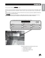
Page 3: ...ing assembly and maintenance instructions Failure to do so could result in personal injury or equipment dam age Keep manuals in a safe place after operator and maintenance personnel have read them Ri...

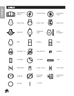
Page 4: ...Open Choke Closed Hand Throttle Hour Meter Hour Meter Fuse Glow Plug Glow Plug Off Glow Plug On RPM Gasoline Diesel Water Temperature Temperature Light Engine Oil Engine Stop Engine Start Engine Run...

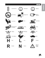
Page 5: ...Parts Manual Operation Pinch Point Step Hot Surface Hydraulic Fluid Penetration Lift Arm Tractor Engage Disengage PTO Ground Speed Fast Slow H High L Low F Forward R Reverse N Neutral Warning Danger...

Page 6: ...n To prevent loss of control or tipping of the vehicle A Use extra caution in backing up the vehicle Ensure area is clear B Do not stop or start suddenly on any slope C Reduce speed on slopes and in s...

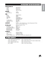
Page 7: ...stor 13 x 5 x 6 20 psi 1 4 bar BATTERY optional Automotive type 45 12 volt BCI Group Size 45 Cold CrankingAmps 480 minimum Ground Terminal Polarity Negative Maximum Length 9 23 cm Maximum Width 5 38 1...

Page 8: ...cting battery cables to the wrong post could result in personal injury and or damage to the electrical system Make sure battery and cables do not interfere or rub on any moving part Connect the red po...

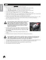
Page 9: ...Never use hands to inspect leaks 4 Check hydraulic fluid level in tank Look at the sight gauge on the front left side of the tank The oil level should be at 90 C 194 F If level is low add SAE 10W 40...

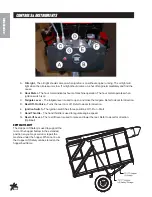
Page 10: ...close the tailgate Refer to decal for direction D Reel Off On Valve Turns the reel on or off Refer to decal for direction E Ignition Switch The ignition switch has three positions Off Run Start F Hand...

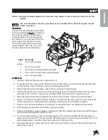
Page 11: ...s needed 7 Check and clean all debris from blower housing ADJUSTMENTOFBELTTENSIONER There are four maximum belt tensioners on the Big Vac Two control the tension on the belts on the blower housing one...

Page 12: ...lyte is added 4 Avoid spilling or dripping electrolyte Battery Electrolyte is an acidic solution and should be handled with care If electrolyte is splashed on any part of your body flush all contact a...

Page 13: ...housing and impeller must be cleaned each time the unit is used so the housing liner is inspected daily Only Smithco Sweeper Vacs provide a clean out inspection port for easy inspection and cleaning 2...

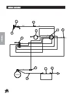
Page 14: ...12 Diagrams WIRINGDRAWING...

Page 15: ...72 Switch Boot 1 3 12 017 Hour Meter 1 4 13 488 Ignition Switch 1 5 78 340 Oil Light 1 6 Plug on Engine 1 7 8975 30Amp Circuit Breaker 1 8977 Circuit Breaker Boot 1 8 48 147 Battery Cable Black 1 9 22...

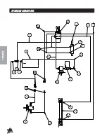
Page 16: ...14 Diagrams HYDRAULICDRAWING...

Page 17: ...72 040 Hydraulic Cylinder 1 72 040 01 Seal Kit 14 23 184 Male Connector 2 15 72 075 Hydraulic Hose 1 16 72 199 Hydraulic Motor 1 17 72 074 Hydraulic Hose 1 18 72 043 Quick Coupler 1 2 Male End 2 19 72...

Page 18: ...16...
Page 19: ...Product Support Hwy SS Poplar Ave Cameron WI 54822 1 800 891 9435 productsupport smithco com Operator s Big Vac Engine Drive 73 000 A SN 73001 January 2006...

Page 20: ...ion 1 Symbols 2 3 Safe Practices 4 Specifications 5 Optional Equipment 5 Setup 6 Overloading Debris Hopper and Vacuum Housing Wear 7 Controls Instruments 8 Operation 9 Battery 10 Diagrams 12 15 Wiring...

Page 21: ...you need help locating an Authorized Smithco Distributor or if you have questions regarding your warranty rights or responsibilities you may contact us at Smithco Product Support Department 200 W Pop...

Page 22: ...warranty gives you specific legal rights and you may also have other rights which vary from state to state THEREARE NO OTHER EXPRESS WARRANTIES OTHER THAN THOSE SET FORTHABOVE ALLIMPLIED WARRANTIES O...

Reviews: