41
Accessories
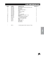
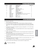
78-205 REMOTE VACUUM HOSE PARTS LIST
REF#
PART#
DESCRIPTION
QUANTITY
1
HBFL-516-18-075
Flange Bolt
5
/
16
- 18 x
3
/
4
1
HNFL-516-18
Flange Whiz Lock Nut
5
/
16
- 18
1
2
78-318
Hose Rack
1
3
HBFL-516-18-075
Flange Bolt
5
/
16
- 18 x
3
/
4
(part of machine)
2
HNFL-516-18
Flange Whiz Lock Nut
5
/
16
- 18
(part of machine)
2
4
78-314
Remote Hose Connector
1
5
78-311
Handle Stop
(part of machine)
1
6
18-340
Hose Clamp
2
7
8970-150
Vacuum Hose 8" x 150"
1
8
HB-14-20-150
Bolt
1
/
4
- 20 x 1
1
/
2
2
HNTL-14-20
Lock Nut
1
/
4
-20
2
9
78-350
Handle Holder
1
8803-17
Trim
1
10
78-354
Hose Handle
1
11
15-019
Round Grip
2
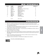
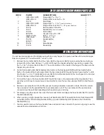
INSTALLATION INSTRUCTIONS
You will need two people and the tailgate open with an empty hopper. One person will have to be inside hopper.
Be sure engine is off. You will need an
11
/
32
and
9
/
32
drill.
1. Remove the two bolts (Ref 3) from the chute. Bolt the hose rack (Ref 2) in place using the two bolts you
removed from the chute. Using an
11
/
32
drill, drill through the hopper using the hose rack as a guide. Use
the
5
/
16
-18 x
3
/
4
bolt and lock nut (Ref 1). The nut should be on the inside of the hopper. The person in the
hopper can get out now.
2. Center the handle holder (Ref 9) between the bends on the brush guard (Ref B) with the handle holder
flush on the inside of the brush guard. Mark the two holes and drill through the brush guard with a
9
/
32
drill.
Use the two
1
/
4
- 20 x 1
1
/
2
bolts and lock nuts (Ref 8) to bolt handle holder to the brush guard. Cut and put
trim into the two notches that hold the hose handle.
3. Connect the hose to the hose handle (Ref 10) with the hose on the same side as the long handle. Then
put other end of hose to remote hose connector (Ref 4). Use the two hose clamps (Ref 6) to hold hose in
place.
4. Remove cover plate from in front of the vacuum housing and place in pocket on chute. Place the remote
hose connector into the pocket that the cover plate came out of. The cover plate and the remote hose
connector must be switched depending which operation you are doing.
5. For storage, loop the vacuum hose over the hose rack (Ref 2) and place the hose handle (Ref 10) into the
handle holder (Ref 9).
6. When you are going to operate the vacuum, pull handle stop (Ref 5) towards the front of machine and lift
up handle (Ref A). While holding handle (Ref A) up, push handle stop (Ref 5) back so that it holds the
handle (Ref A) up.
7. You may want to remove the hose handle, hose and remote hose connector if you are not going to use the
vacuum for an extended amount of time.
Summary of Contents for 78-200
Page 14: ...12 Diagrams WIRINGDRAWING...
Page 16: ...14 Diagrams HYDRAULICDRAWING...
Page 18: ...16 Parts BODYANDFRAMEDRAWING...
Page 20: ...18 Parts ENGINEANDCONTROLSDRAWING...
Page 22: ...20 Parts PULLEYANDPUMPDRAWING...
Page 24: ...22 Parts BLOWERANDVACUUMHOUSINGDRAWING...
Page 26: ...24 Parts FINGERREELDRAWING...
Page 28: ...26 Parts BRUSHREELDRAWING...
Page 30: ...28 Parts REEL HYDRAULICPUMPDRAWING...
Page 32: ...30 Parts HOPPERDRAWING...
Page 34: ...32 Parts HOPPERDRAWING...
Page 36: ...34 Parts 78 4152 BANKVALVEDRAWING...
Page 38: ...36 Parts REAR AXLE ELECTRIC BRAKE PARTS LIST...
Page 40: ...38 Accessories 78 201 REPLACEMENTBRUSHREELDRAWING 78 202REPLACEMENTFINGERREELDRAWING...
Page 42: ...40 Accessories 78 205REMOTEVACUUMHOSEDRAWING...
Page 44: ...42 Accessories 78 2045TH WHEELHITCHDRAWING Do not tow on public roads...
Page 46: ...44 Accessories 78 206CLEVISHITCHDRAWING...
Page 48: ...46 Accessories 78 209BALLHITCHDRAWING...
Page 50: ...48 Accessories 78 207HYDRAULICLIFTKITDRAWING...
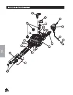
Page 52: ...50 Accessories 78 4163 BANKHYDRAULICVALVEDRAWING...
Page 54: ...52 Accessories 78 208FILTERSYSTEMDRAWING...
Page 56: ...54 Accessories 78 210 78 211REELANDHYDRAULICPUMPDRAWING...
Page 58: ...56 Accessories 78 210NYLONBRUSHHEADDRAWING...
Page 60: ...58 Accessories 78 211RUBBERFINGERHEADDRAWING...
Page 62: ...60 NOTES...

