45
Accessories
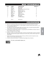
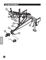
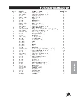
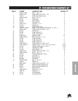
78-206 CLEVIS HITCH PARTS LIST
REF#
PART#
DESCRIPTION
QUANTITY
1
78-244
3
/
4
" Clevis
1
2
78-268
Hitch Insert
1
3
78-267
Tongue
1
HB-12-13-350
Bolt
1
/
2
- 13 x 3
1
/
2
1
HNTL-12-13
Lock Nut
1
/
2
- 13
1
4
HBFL-516-18-075
Flange Bolt
5
/
16
-18 x
3
/
4
4
HNFL-516-18
Flange Whiz Lock Nut
5
/
16
-18
4
5
78-299
Adjustment Slide
1
6
78-295
Adjustment Lock
2
15-020
Hand Grip
2
7
78-298
Control Panel Adjustment
1
8
78-312
Control Panel Mount
1
9
HSTP-14-20-075
Phillips Truss Machine Screw
1
/
4
- 20 x
3
/
4
(part of machine)
4
HNFL-14-20
Flange Whiz Lock Nut
1
/
4
-20
(part of machine)
4
10
HB-12-13-125
Bolt
1
/
2
- 13 x 1
1
/
4
4
HNTL-12-13
Lock Nut
1
/
2
- 13
4
11
HB-58-11-450
Bolt
5
/
8
- 11 x 4
1
/
2
(part of 78-244)
2
HNCL-58-11
Center Lock Nut
5
/
8
- 11
(part of 78-244)
2
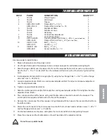
INSTALLATION INSTRUCTIONS
Use two people to install hitches.
1. Block both wheels so machine does not roll.
2. Use the jack that is part of the sweeper to raise or lower sweeper to comfortable working height.
3. Slide the tongue (Ref 3) over the tabs on the front of the sweeper frame. Hitch must be on the outside.
Use the four
1
/
2
- 13 x 1
1
/
4
bolts (Ref 10) on the outside and four lock nuts on the inside. Tighten all four
bolts.
4. Install adjustment slide (Ref 5) to tongue (Ref 3) using the four flange bolts
1
/
4
- 20 x
3
/
4
and four flange
whiz lock nuts
1
/
4
- 20 (Ref 4).
5. Loosen adjustment locks (Ref 6) on control panel adjustment (Ref 7) and put control panel adjustment
onto the adjustment slide.
6. Tighten one adjustment lock (Ref 6).
7. Slide the control panel mount (Ref 8) through the control panel adjustment (Ref 7) and tighten the other
adjustment lock (Ref 6).
8. The control panel has all the hoses, wiring and throttle cable connected to it and to the sweeper. The
control panel is wrapped and fastened to the front of the sweeper.
9. Remove the control panel from the sweeper, bring it forward with the hoses to the rear and the throttle on
the left hand side.
10. Fasten the control panel to the control panel mount with the four truss head machine screws
1
/
4
- 20 x
3
/
4
and four flange whiz lock nuts
1
/
4
- 20 (Ref 9).
11. Put the two handles onto the valve and tighten the lock nuts with the handles pointing forward.
12. Place three hoses and the throttle cable on the left hand side of the adjustment slide.
Do not tow on public roads.
Summary of Contents for 78-200
Page 14: ...12 Diagrams WIRINGDRAWING...
Page 16: ...14 Diagrams HYDRAULICDRAWING...
Page 18: ...16 Parts BODYANDFRAMEDRAWING...
Page 20: ...18 Parts ENGINEANDCONTROLSDRAWING...
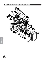
Page 22: ...20 Parts PULLEYANDPUMPDRAWING...
Page 24: ...22 Parts BLOWERANDVACUUMHOUSINGDRAWING...
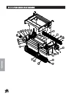
Page 26: ...24 Parts FINGERREELDRAWING...
Page 28: ...26 Parts BRUSHREELDRAWING...
Page 30: ...28 Parts REEL HYDRAULICPUMPDRAWING...
Page 32: ...30 Parts HOPPERDRAWING...
Page 34: ...32 Parts HOPPERDRAWING...
Page 36: ...34 Parts 78 4152 BANKVALVEDRAWING...
Page 38: ...36 Parts REAR AXLE ELECTRIC BRAKE PARTS LIST...
Page 40: ...38 Accessories 78 201 REPLACEMENTBRUSHREELDRAWING 78 202REPLACEMENTFINGERREELDRAWING...
Page 42: ...40 Accessories 78 205REMOTEVACUUMHOSEDRAWING...
Page 44: ...42 Accessories 78 2045TH WHEELHITCHDRAWING Do not tow on public roads...
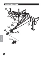
Page 46: ...44 Accessories 78 206CLEVISHITCHDRAWING...
Page 48: ...46 Accessories 78 209BALLHITCHDRAWING...
Page 50: ...48 Accessories 78 207HYDRAULICLIFTKITDRAWING...
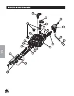
Page 52: ...50 Accessories 78 4163 BANKHYDRAULICVALVEDRAWING...
Page 54: ...52 Accessories 78 208FILTERSYSTEMDRAWING...
Page 56: ...54 Accessories 78 210 78 211REELANDHYDRAULICPUMPDRAWING...
Page 58: ...56 Accessories 78 210NYLONBRUSHHEADDRAWING...
Page 60: ...58 Accessories 78 211RUBBERFINGERHEADDRAWING...
Page 62: ...60 NOTES...

