background image

6

Service

MAINTENANCE 

(CONTINUED)

BATTERY

Batteries normally produce explosive gases which can cause personal injury. Do not allow flames, sparks or any
ignited object to come near the battery. When charging or working near battery, always shield your eyes and
always provide proper ventilation.

Battery cable should be disconnected before using “Fast Charge”.

Charge battery at 15 amps for 10 minutes or 7 amps for 30 minutes. Do not exceed the recommended charging
rate. If electrolyte starts boiling over, decrease charging.

Always remove grounded (-) battery clamp first and replace it last. Avoid hazards by:

1. Filling batteries in well-ventilated areas.

2. Wear eye protection and rubber gloves.

3. Avoid breathing fumes when electrolyte is added.

4. Avoid spilling or dripping electrolyte.

Battery Electrolyte is an acidic solution and should be handled with care. If electrolyte is
splashed on any part of your body, flush all contact areas immediately with liberal amounts
of water. Get medical attention immediately.

JUMP STARTING

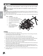
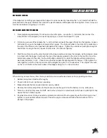
Use of booster battery and jumper cables. Particular care should be used when connecting a
booster battery. Use proper polarity in order to prevent sparks.

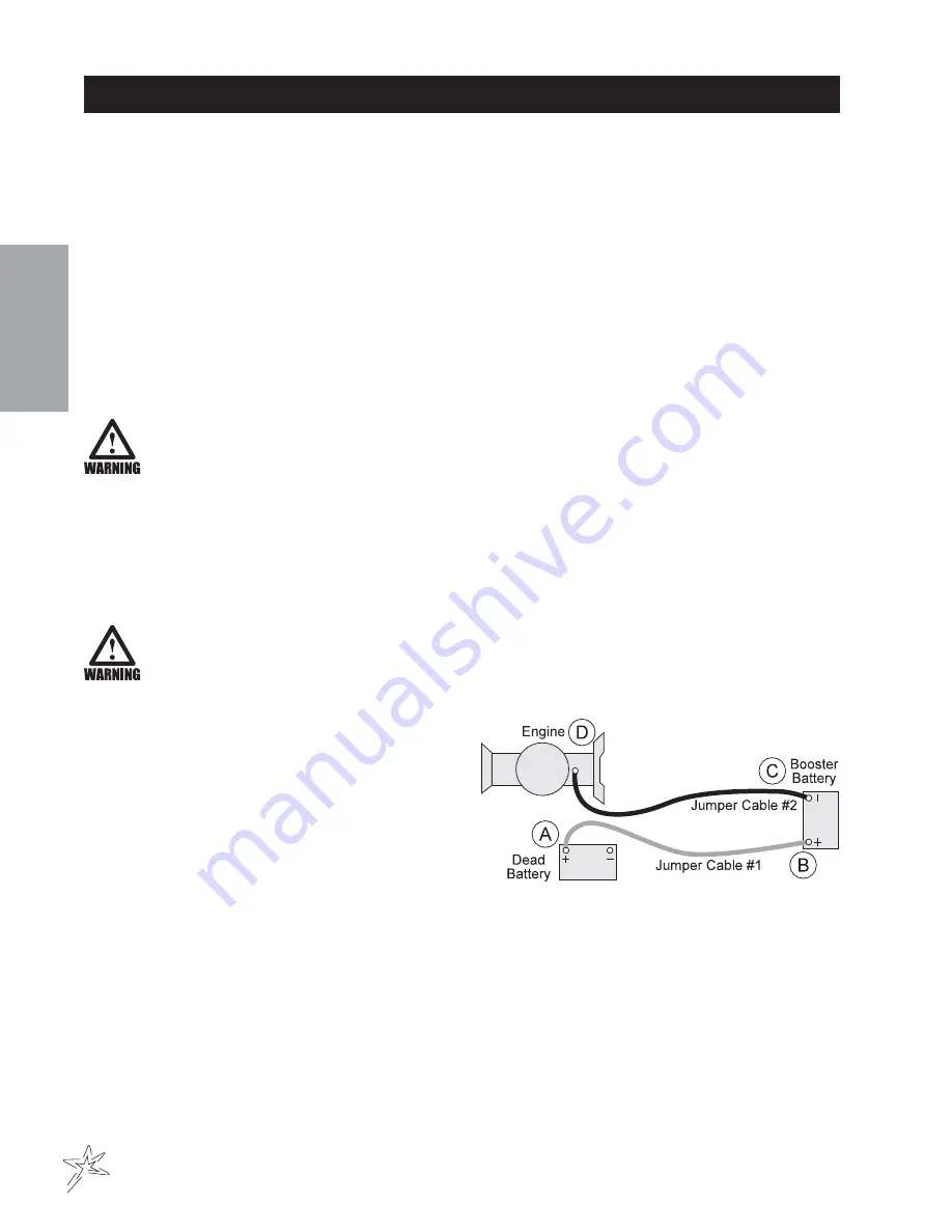
To jump start (negative grounded battery):

1. Shield eyes.

2. Connect ends of one cable to positive (+) termi-

nals of each battery, first (A) then (B).

3. Connect one end of other cable to negative (-)

terminal of "good" battery (C).

4. Connect other end of cable (D) to engine block on

unit being started (NOT to negative (-) terminal of
battery)

To prevent damage to other electrical components on
unit being started, make certain that engine is at idle speed before disconnecting jumper cables.

Summary of Contents for 78-200

Page 1: ...SweepStar V62 with Electric Clutch 78 200 SN 78595 January 2012 Product Support Hwy SS Poplar Ave Cameron WI 54822 1 800 891 9435 productsupport smithco com Parts Service...

Page 2: ...m Housing 22 23 Finger Reel 24 25 Brush Reel 26 27 Reel and Hydraulic Pump 28 29 Hopper 30 33 78 415 2 Bank Hydraulic Valve 34 35 Rear Axle Electric Brake 36 37 Accessories 38 59 78 201 Replacement Br...

Page 3: ...thco Smithco machines have a Serial Number and Model Number Both numbers are needed when ordering parts Refer to engine manual for placement of engine serial number For product and accessory informati...

Page 4: ...xtra caution in backing up the vehicle Ensure area is clear B Do not stop or start suddenly on any slope C Reduce speed on slopes and in sharp turns Use caution when changing directions on slopes D St...

Page 5: ...Automotive type 45 12 volt BCI Group Size 45 Cold CrankingAmps 480 minimum Ground Terminal Polarity Negative Maximum Length 9 23 cm Maximum Width 5 38 14 cm Maximum Height 9 23 cm FLUIDCAPACITY Crank...

Page 6: ...hours or annually which ever is first and change the filter after the first 50 hours then every 250 hours thereafter 3 The oil level should be 2 to 21 2 from top of the tank when fluid is cold Do not...

Page 7: ...il with gasoline WHEELMOUNTINGPROCEDURE MACHINE WHEELS 1 Turn machine off and remove key 2 Be sure unit is on a level surface Unhitch from tow vehicle if possible 3 Block the opposite wheel then the o...

Page 8: ...ctrolyte is added 4 Avoid spilling or dripping electrolyte Battery Electrolyte is an acidic solution and should be handled with care If electrolyte is splashed on any part of your body flush all conta...

Page 9: ...er cores is Model 72 000 Big Vac 12 in 30 cm Model 78 200 78 500 Sweep Star V62 40 in 101 cm VACUUMHOUSINGWEAR Smithco Sweeper Vacs are fitted with a wear resistant liner in the vacuum housing This wi...

Page 10: ...ratures maintenance should be more frequent Duplicate this page for routine use Mon Tues Wed Thurs Fri Sat Sun Check the Safety Seat Switch Check Steering Operation Check the fuel level Check the engi...

Page 11: ...r change remote air cleaner Check the battery fluid level and cable connections Service exhaust sytem Check belt tension Check engine valve clearance and adjust if necessary Check idle speed Clean bat...

Page 12: ...to the best of its ability To adjust belt tensioner loosen bolt holding tensioner Bring idler pulley tight to belts and turn tensioner into belts to 15 Tighten holder bolt CASTORWHEELS Install castor...

Page 13: ...comes in contact with the hopper it will push the top of the tailgate outward in the slots in the top lift arm as the bolts slide outward in the slots As the bolts slide outward in the slots the tailg...

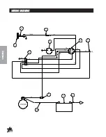
Page 14: ...12 Diagrams WIRINGDRAWING...

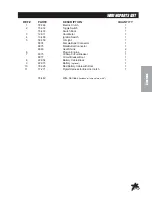
Page 15: ...1 5 50 359 Oil Light 1 8874 Female Bullet Connector 1 8875 Male Bullet Connector 1 8963 Heat Shrink 2 6 Plug on Engine 1 7 8975 30Amp Circuit Breaker 1 8977 Circuit Breaker Boot 1 8 22 054 Battery Ca...

Page 16: ...14 Diagrams HYDRAULICDRAWING...

Page 17: ...78 415 2 Bank Hydraulic Valve 1 7 78 246 Hydraulic Hose rear hyd cyl to front valve 1 8 78 248 Hydraulic Hose front hyd cyl to rear valve 1 9 13 584 Oil Tank 1 10 8917 14 Suction Hose 5 8 ID x 14 1 1...

Page 18: ...16 Parts BODYANDFRAMEDRAWING...

Page 19: ...pper Door 1 14 HNFL 38 16 Flange Whiz Lock Nut 3 8 16 4 15 78 264 Left Door Arm 1 16 19 205 Spring 2 17 HB 38 16 575 Bolt 3 8 16 x 53 4 2 18 78 387 Weatherstripping Bracket 2 8979 61 Door Weatherstrip...

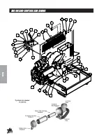
Page 20: ...18 Parts ENGINEANDCONTROLSDRAWING...

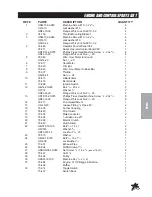
Page 21: ...3 488 Ignition Switch 1 12 HB 14 20 200 Bolt 1 4 20 x 2 2 HW 14 Washer 1 4 2 HNFL 14 20 Flange Whiz Lock Nut 1 4 20 2 13 HSTP 14 20 075 Phillips Truss Head Machine Screw 1 4 20 x 3 4 8 HNFL 14 20 Flan...

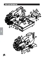
Page 22: ...20 Parts PULLEYANDPUMPDRAWING...

Page 23: ...ulley 3 Groove pump 1 11 78 413 Hydraulic Pump 1 HWK 316 063 Woodruff Key 3 16 x 5 8 1 HB 38 16 150 Bolt 3 8 16 x 11 2 2 HW 38 Washer 3 8 4 HNTL 38 16 Lock Nut 3 8 16 2 12 23 006 Oil Filter 1 23 031 R...

Page 24: ...22 Parts BLOWERANDVACUUMHOUSINGDRAWING...

Page 25: ...075 Flange Bolt 5 16 18 x 3 4 11 HNTL 516 18 Top Lock Nut 5 16 18 11 14 78 301 Balanced Fan 1 15 78 347 Spiral Spring Pin 2 16 25 120 Handle Grip 1 17 78 243 Sweeper Boot 1 18 HBFL 38 16 075 Flange Bo...

Page 26: ...24 Parts FINGERREELDRAWING...

Page 27: ...1 2 x 14GA 8 21 HNTL 12 13 Lock Nut 1 2 13 4 22 72 056 Plastic Belt Guard 1 23 HST 14 20 075 Truss Head Machine Screw 1 4 20 x 3 4 4 HNFL 14 20 Flange Whiz Lock Nut 1 4 20 4 24 42 202 Tire Wheel 4 42...

Page 28: ...26 Parts BRUSHREELDRAWING...

Page 29: ...8 322 Strip Brush 1 20 42 213 Axle Bearing 4 21 42 212 Castor Wheel Spacer 8 HMB 34 10 Machine Bushing 3 4 x 10GA 8 22 HNTL 12 13 Lock Nut 1 2 13 4 23 72 056 Plastic Belt Guard 1 24 HSTP 14 20 075 Tru...

Page 30: ...28 Parts REEL HYDRAULICPUMPDRAWING...

Page 31: ...racket 1 17 HBFL 516 18 075 Flange Bolt 5 16 18 x 3 4 2 HNFL 516 18 Flange Whiz Lock Nut 5 16 18 2 18 72 056 Plastic Belt Guard 1 19 HSTP 14 20 075 Truss Head Machine Screw 1 4 20 x 3 4 4 78 274 Cage...

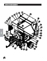
Page 32: ...30 Parts HOPPERDRAWING...

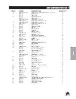
Page 33: ...per 1 10 78 262 Chute 1 11 78 304 Battery Hold Down 1 HWL 14 Lockwasher 1 4 2 HN 14 20 Nut 1 4 20 2 12 HBFL 516 18 075 Flange Bolt 5 16 18 x 3 4 12 HNFL 516 18 Flange Whiz Lock Nut 5 16 18 12 13 22 07...

Page 34: ...32 Parts HOPPERDRAWING...

Page 35: ...386 Hopper Filter 1 33 78 382 Screen 1 34 78 385 Wear Strip Bracket 2 8946 42 Wear Strip 42 2 35 HSD 8 050 Pan Head Drill Screw 8 x 1 2 14 36 HSM 10 32 100 Machine Screw 10 32 x 1 2 HWL 10 Lockwasher...

Page 36: ...34 Parts 78 4152 BANKVALVEDRAWING...

Page 37: ...8 415 06 AType Spool HDS11 3 7 78 415 07 Positioner 2 8 78 415 08 Plug 3 9 78 415 09 Lever Group HDS11 3 10 78 415 10 Metric Socket Screw M5 x 8 x 45 6 11 78 415 11 Positioner 1 12 78 415 12 Check Val...

Page 38: ...36 Parts REAR AXLE ELECTRIC BRAKE PARTS LIST...

Page 39: ...7 16 20 nuts and lockwashers Ref 10 3 Then place the hub and drum assembly Ref 3 over the brake Be sure to install the grease seal Ref 2 and the bearing cup and cone Ref 5 as shown in the drawing 4 Pu...

Page 40: ...38 Accessories 78 201 REPLACEMENTBRUSHREELDRAWING 78 202REPLACEMENTFINGERREELDRAWING...

Page 41: ...1 2 6 78 321 Spiral Brush 1 78 202REPLACEMENTFINGERREELPARTSLIST REF PART DESCRIPTION QUANTITY 1 HB 38 16 125 Bolt 3 8 16 x 11 4 8 HNFL 38 16 Flange Whiz Lock Nut 3 8 16 8 2 78 222 Mounted Bearing 2 3...

Page 42: ...40 Accessories 78 205REMOTEVACUUMHOSEDRAWING...

Page 43: ...Center the handle holder Ref 9 between the bends on the brush guard Ref B with the handle holder flush on the inside of the brush guard Mark the two holes and drill through the brush guard with a 9 3...

Page 44: ...42 Accessories 78 2045TH WHEELHITCHDRAWING Do not tow on public roads...

Page 45: ...he sweeper frame Hitch must be on the outside Use the four 1 2 13 x 11 4 bolts Ref 7 on the outside and four lock nuts on the inside Tighten all four bolts 4 Install the control panel mount Ref 3 on t...

Page 46: ...44 Accessories 78 206CLEVISHITCHDRAWING...

Page 47: ...st be on the outside Use the four 1 2 13 x 11 4 bolts Ref 10 on the outside and four lock nuts on the inside Tighten all four bolts 4 Install adjustment slide Ref 5 to tongue Ref 3 using the four flan...

Page 48: ...46 Accessories 78 209BALLHITCHDRAWING...

Page 49: ...4 bolts Ref 10 on the outside and four lock nuts on the inside Tighten all four bolts 4 Install adjustment slide Ref 5 to tongue Ref 3 using the four flange bolts 1 4 20 x 3 4 and four flange whiz loc...

Page 50: ...48 Accessories 78 207HYDRAULICLIFTKITDRAWING...

Page 51: ...0GA 1 5 78 365 Adapter with Orifice 1 78 364 Hydraulic Hose 1 6 HHP 18 Bridge Pin 1 8 1 7 18 169 Adapter 3 8 1 78 364 Hydraulic Hose 1 8 14 534 Hydraulic Cylinder 1 14 529 Seal Kit 1 9 HB 38 16 200 Bo...

Page 52: ...50 Accessories 78 4163 BANKHYDRAULICVALVEDRAWING...

Page 53: ...HDS11 2 7 78 415 11 Positioner HDM10 2 8 78 415 08 Plug 3 9 78 415 09 Lever Group HDS11 3 10 78 415 10 Metric Socket Screw M5 x 8 x 45 6 11 78 415 07 Positioner 1 12 78 415 12 Check ValveAssembly HDM1...

Page 54: ...52 Accessories 78 208FILTERSYSTEMDRAWING...

Page 55: ...53 Accessories 78 208FILTERSYSTEMPARTSLIST REF PART DESCRIPTION QUANTITY 1 78 288 Filter Case 1 2 78 328 Filter 1...

Page 56: ...54 Accessories 78 210 78 211REELANDHYDRAULICPUMPDRAWING...

Page 57: ...ket 1 17 HBFL 516 18 075 Flange Bolt 5 16 18 x 3 4 2 HNFL 516 18 Flange Whiz Lock Nut 5 16 18 2 18 72 056 Plastic Belt Guard 1 19 HST 14 20 075 Truss Head Machine Screw 1 4 20 x 3 4 4 HNFL 14 20 Flang...

Page 58: ...56 Accessories 78 210NYLONBRUSHHEADDRAWING...

Page 59: ...1 12 78 321 Spiral Brush 1 13 HNTL 12 13 Lock Nut 1 2 13 4 14 42 202 Tire and Wheel 4 42 202 01 Tire 9 x 3 5 x 4 Ply 4 42 202 02 Wheel 4 42 202 03 Cap 4 42 202 04 Bearing 8 42 202 05 Seal 8 15 78 434...

Page 60: ...58 Accessories 78 211RUBBERFINGERHEADDRAWING...

Page 61: ...ey 1 4 x 1 4 x 1 1 17 78 303 Finger Reel Bar 1 18 78 297 Finger Clamp 10 17 19 78 326 Finger Clamp 12 1 20 HNFL 516 18 Flange Whiz Lock Nut 5 16 18 40 21 HG 14 28 180 Grease Fitting 1 4 28 x 180 part...

Page 62: ...60 NOTES...
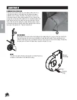
Page 63: ...ning Hot Muffler 25 307 Decal Refueling w Gasoline Above Gas Tank 25 344 Decal 3 Star Right Side Belt Guard 25 355 Decal Tire Pressure 18 psi Rear Wheels 25 356 Decal Tire Pressure 20 psi Castor Forks...

Page 64: ...4 529 Seal Kit 15 839 Tailgate Cylinder 14 531 Seal Kit 78 415 2 Bank Hydraulic Valve 78 415 03 Seal Kit 78 413 Hydraulic Pump 78 413 01 Seal Kit OTHERPARTS Spark Plug NGK BMR 6A or equivalent Gap 024...

Page 65: ...fe operation of this product at your location Instructions for Obtaining Warranty Service You are responsible for notifying the Authorized Smithco Products Distributor from whom you purchased the Prod...

Page 66: ...cturers if inspection by the original component manufacturer indicates that failure was due to normal wear and tear expected consumption through use or improper care or service Other Legal Disclaimers...

Reviews: