background image

SAFE PRACTICES 


1.  

It is your responsibility to read this manual and all publications associated with this 
machine (engine and accessories). 

2.   Never allow anyone to operate or service the machine or its accessories without proper 

training and instructions. Never allow minors to operate any equipment. 

3.   Learn the proper use of the machine, the locations and purpose of all the controls  before 

you operate the equipment. Working with unfamiliar equipment can lead to accidents. 

4.   Wear all the necessary protective clothing and personal safety devises to protect your head, 

eyes, ears, hands and feet. Operate the machine only in daylight or in good artificial light. 

5.   Inspect the area where the equipment will be used. Pick up all debris you can find before 

operating. Beware of overhead obstructions and underground obstacles. Stay alert for 
hidden hazards. 

6.   Never operate equipment that is not in perfect working order or without decals, guards, 

shields, or other protective devices in place. 

7.  

Never disconnect or bypass any switch. 

8.   Carbon monoxide in the exhaust fumes can be fatal when inhaled, never operate a machine 

without proper ventilation. 

9.   Fuel is highly flammable, handle with care. 
10. Keep engine clean. Allow the engine to cool before storing and always remove the ignition 

key. 

11. After engine has started machine must not move. If movement is evident, the neutral 

mechanism is not adjusted correctly. Shut engine off and readjust so the machine does not 
move when in neutral position. 

12. Never use your hands to search for oil leaks. Hydraulic fluid under pressure can penetrate 

the skin and cause serious injury. 

13. This machine demands your attention. To prevent loss of control or tipping of the vehicle: 

Use extra caution in backing up the vehicle. Make sure area is clear. Do not stop or 

start suddenly on any slope. Avoid driving sideways on hills as much as possible. 

Reduce speed on slopes and in sharp turns. Use caution when changing directions on 

slopes. 

Stay alert for holes in the terrain and other hidden hazards. 

14. 

Before leaving operator’s position for any reason: 

Disengage all drives. 
Shut engine off and remove the ignition key. 

15. Keep hands, feet and clothing away from moving parts. Wait for all movement to stop before 

you clean, adjust or service the machine. 

16. Keep the area of operation clear of all bystanders. 
17. Never carry passengers. 
18. Stop engine before making repairs/adjustments or to check or add oil to the crankcase. 
19. 

Use parts and materials supplied by SMITHCO only. Do not modify any function or 

part. 

 
These machines are intended for professional maintenance on flat grass athletic fields. Other 
use will void the warranty. 


Summary of Contents for SLN270

Page 1: ...SUPER LINER 44 901 SN SLN270 Revised March 2014 Product Support 1020 Hwy 224 Humboldt KS 66748 1 888 422 5173 lj smithco com Wayne PA 19087 www smithco com Owner s Manual ...

Page 2: ...n Frame Drawing 6 Main Frame Parts List 7 8 Engine Pump Drawing 9 Engine Pump Parts List 10 Steering Drawing 11 Steering Parts List 12 Hydraulic Hose Diagram 13 Hydraulic Hose Parts List 14 Plumbing Drawing 15 Plumbing Parts List 16 17 Frame Tank Drawing 18 Frame Tank Parts List 19 Wiring Diagram 20 Wiring Parts List 21 49 028 Side Line Boom Drawing Parts List 22 Warranty ...

Page 3: ...l have read them Right and left sides are from the operator s seat facing forward All SMITHCO machines have a Serial Number and Model Number Both numbers are needed when ordering parts The serial number plate on the 44 901 Super Liner is located under the tank on the left side wall of the tank mount For easy access record your Serial and Model numbers here Information needed when ordering replacem...

Page 4: ...ool before storing and always remove the ignition key 11 After engine has started machine must not move If movement is evident the neutral mechanism is not adjusted correctly Shut engine off and readjust so the machine does not move when in neutral position 12 Never use your hands to search for oil leaks Hydraulic fluid under pressure can penetrate the skin and cause serious injury 13 This machine...

Page 5: ...5m 53 dbA at 100 30m 50 dbA Controls Forward Reverse hand control Brakes Dynamic braking through hydrostatic system Seat High Back one piece for operator comfort Main Frame Hydraulically formed electrically welded heavy wall steel tubing Ground Speed Infinitely variable 0 12 mph 0 16kph Engine 16 hp 12 kW Vanguard V twin cylinder air cooled gasoline cast iron sleeves 29 3cu in displacement electro...

Page 6: ...ocated at the rear of the tank Drain remaining paint into a resealable container using the hose provided Drain and replace the strainer B Flush the paint tank with fresh water for 5 minutes with the drain valve open until all the paint residue is out of the tank C Close the ball valve at the bottom of the tank Connect the hose from the gate valve to a clean water source D Turn the selector valve t...

Page 7: ...variables affecting the line density if it is not satisfactory A Paint may be inferior Paint mixture may be too thick or too thin B Hoses or tips may be clogged Tips must be clean System may need to be flushed or paint may need to be restrained C Nozzle tips may be worn out Replace with TeeJet 8002EVS stainless steel D Reducing speed increases paint applied Increasing speed decreases paint applied...

Page 8: ...44 901 MAIN FRAME DRAWING 6 ...

Page 9: ...8 Hex Nut 2 19 19 674 Spring 1 20 44 950 Upper Strap 2 21 400 005 5 16 x 1 Bolt 4 22 44 951 Lower Strap 2 23 400 255 Elevator Bolt 4 24 400 102 5 16 Hex Nut 8 25 44 963 Battery Box 1 26 400 044 x 1 Bolt 3 27 400 101 Hex Nut 2 28 400 002 5 16 x 1 Bolt 3 29 400 003 5 16 x 1 Bolt 1 30 400 102 5 16 Hex Nut 1 31 44 942 Step 1 32 44 925 Main Frame 1 33 44 919 Taper Hub 5 Bolt 2 34 44 911 1 Rear Tire Onl...

Page 10: ...ront Axle Pin 1 58 44 931 Main Front Axle 1 59 44 977 King Pin 2 60 44 921 Front Axle Left 1 61 720 043 Cotter Pin 2 62 44 978 Slotted Nut 2 63 709 171 Seal 2 64 2028 Bearing 4 65 44 923 Front Hub 1 66 720 043 Cotter Pin 2 67 709 126 Spindle Nut 2 68 44 937 Front Tire Wheel 2 69 1187 Lug Nut 20 70 2024 Dust Cap 2 71 44 974 Motor Switch Plate 1 72 44 763 Parking Brake Lever 1 73 44 1001 Brake Brack...

Page 11: ...44 901 ENGINE PUMP DRAWING 9 ...

Page 12: ... 44 912 Gas Tank 1 13 943 241 Carbon Canister 1 14 943 240 Carbon Canister Mount 1 15 638 Purge Line 13 1 16 638 Vent Line 12 1 17 943 159 Oil Filter Adapter 1 18 943 104 Oil Filter 1 19 44 912 1 Fuel Cap 1 20 44 912 2 Fuel Fitting 1 21 943 110 4 Vent Valve 2 22 44 983 Barb Tee 1 23 638 Vent Line 12 1 24 638 Vent Line 1 1 25 400 202 5 16 Flat Washer 6 26 400 209 3 8 Lock Washer 6 27 400 090 3 8 x ...

Page 13: ...44 901 STEERING DRAWING 11 ...

Page 14: ...13 1088 3 16 x 1 Key 5 14 750 266 Steering Sprocket Shaft 1 15 520 007 Bronze Bushing 2 16 750 195 Steering Tube 1 17 400 005 5 16 x 1 Bolt 2 18 400 109 5 16 Lock Nut 2 19 41 194 Chain Adjuster 1 20 1036 Bearing 1 21 750 106 Steering Column 1 22 400 055 5 16 x 3 Bolt 4 23 400 207 5 16 Lock Washer 8 24 400 073 x 1 Drill Screw 4 25 750 107 Steering Column Cover 1 26 1075 40 Jackshaft Sprocket 11T 1 ...

Page 15: ...44 901 HYDRAULIC HOSE DIAGRAM 13 ...

Page 16: ...w 8 90 St 1 12 44 996 8 HPH 8 w 8 90 St 1 13 750 208 8 90 2 14 750 205 6 to 6 St 3 15 44 958 4 to 6 St 2 16 44 959 3 8 MNPT x 6 x 6 1 17 44 877 3 8 MNPT x 8 St 1 18 750 325 12 x 8 St 2 19 750 302 Filter Head 1 20 44 997 12 x 6 St 2 21 750 848 8 x 8 St 1 22 44 961 6 x 6 90 1 23 44 960 6 Tee 1 24 44 962 8 Tee 2 25 750 326 10 x 6 St 4 26 750 801 Wheel Motor 2 27 44 918 Motor Switch 1 28 44 917 Pump M...

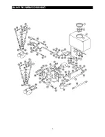
Page 17: ...44 901 PLUMBING DRAWING 15 ...

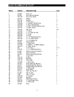
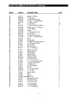
Page 18: ...2 Drain Support 1 20 709 287 Gate Valve 1 21 707 050 MGHT x MNPT Adapter 1 22 709 314 Hose Clamp 4 23 647 LP Hose 5 24 709 341 x Barb Elbow Poly 2 25 44 865 Strainer Aluminum Nylon 1 26 44 947 Clean out Hose 1 27 44 949 Strainer Mounting Bracket 1 28 647 LP Hose 6 29 106 110 O Ring 1 30 106 108 Barb Nut 1 31 106 107 Hose Barb 1 32 709 265 Ball Valve 1 33 44 939 Pump Mounting Bracket 1 34 44 973 Si...

Page 19: ...ace 2 64 44 811 3 Way Ball Valve 1 65 44 908 Boom Hose 1 66 41 118 Electric Valve 1 67 500 111 x Bushing 1 68 18 011 Nipple Close 1 69 41 119 Plug w Wires 1 70 44 876 Valve Elbow 1 71 44 907 Supply Hose 1 72 44 875 Strainer Fitting 1 73 500 400 Elbow Gal 2 74 44 879 Boom Box Fitting 2 75 44 888 x 13 Boom Box Hose 2 76 44 878 Boom Box Elbow 2 77 18 012 Brass Tee 2 78 18 011 Close Nipple 2 79 44 007...

Page 20: ...44 901 FRAME TANK DRAWING 18 ...

Page 21: ...de Boom Lift Arm 1 18 44 967 5 16 FT Tie Rod End 4 19 44 975 Side Boom Lift Rod 1 20 400 123 Wing Nut 8 21 400 060 5 16 x 1 Thumb Screw 4 22 44 944 Front Lift Rod 1 23 44 305 1 Boom Flapper 4 24 44 971 Side Boom Box 1 25 750 366 Steering Mechanism 1 26 750 715 Throttle Cable 1 27 2550 Handle Grip 2 28 2081 1 Key f Ignition Switch 1 29 932 071 Key Switch 1 30 943 126 Choke Cable 1 31 2110 Bushing 2...

Page 22: ...SUPER LINER WIRING DIAGRAM 20 ...

Page 23: ...Seat Switch 1 3 943 100 16hp Engine 1 4 44 873 Hour Meter 1 5 Battery 1 6 932 072 Solenoid 1 7 44 935 Wiring Harness 1 8 942 049 Wiring Harness for Seat Switch 1 9 41 119 Plug with Wires 1 10 41 118 Electric Valve 1 11 44 943 Pump Switch 1 12 44 722 Paint Switch 1 13 44 918 Motor Switch 1 21 ...

Page 24: ...ost Bearing 2 4 49 031 Boom Arm 1 5 44 007 Socket 1 6 709 303 NPT x Barb Brass 1 7 709 312 Hose Clamp 4 8 642 PVC Hose Orange 40 9 709 056 Brass Tee 1 10 709 048 Strainer 2 11 709 063 Square Clamp 2 12 709 080 TKSS3Spray Tip SS TKSS3 2 13 19 680 Brass Nozzle Cap 2 14 709 057 Brass Elbow 1 15 610 221 Black Cap 1 NOTE Tip spacing is 20 apart 22 ...

Page 25: ... at your location Instructions for Obtaining Warranty Service You are responsible for notifying the Authorized Smithco Products Distributor from whom you purchased the Product as soon as you believe a warrantable condition exists and not later than 30 days from discovery of the condition If you need help locating an Authorized Smithco Distributor or if you have questions regarding your warranty ri...

Page 26: ...ue to normal wear and tear expected consumption through use or improper care or service Other Legal Disclaimers The above remedy for product defects through repair or replacement by an authorized Smithco distributor or dealer is the purchaser s sole remedy for any defect This warranty gives you specific legal rights and you may also have other rights which vary from state to state THERE ARE NO OTH...

Page 27: ......

Reviews: