12
Operation
OPERATION
(CONTINUED)
SPRAYER VALVE SETTINGS AND SPRAY TANK AGITATION
The gate valve on the suction side of the pump, between the tank and the pump must be open before pump is
engaged. Close this valve only when necessary to clean the filter with spray material in the spray tank.
There is a manual flow control valve on the discharge side of the spray system that controls the agitator. This
valve may be opened as much as necessary to provide hydraulic agitation through the quadrajet agitator in the
tank bottom. This valve may be partially closed to prevent or reduce foam buildup from the spray materials inside
the tank. When the liquid level in the spray tank reaches a certain level (usually 1-25 gallons (3.8-95 Liters)
depending on terrain and other conditions) it may be necessary to close the valve in the agitator line in order to
prevent loss of suction prime.
If your Spray Star is fitted with a hose reel, there is a second ball valve on the discharge system to supply material to
the hose reel.
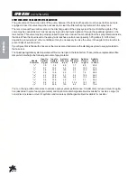
The Quadrajet agitation system operates with four venturi jets in the tank bottom. These jets have replaceable orifice
discs which discharge the following amounts of spay material.
Input to
Input to
Agitator
Agitator
Agitator
Agitator
Nozzle
Agitator
Agitator
Pressure Pressure
Output
Output
Diameter
in gpm
in L/min
in psi
in bar
in gpm
in L/min
1
/
8
"
1.9
7.2
25
1.7
6.3
23.8
1
/
8
"
2.7
10.2
50
3.4
10.0
37.9
1
/
8
"
3.8
14.4
100
6.9
15.0
56.8
5
/
32
"
2.8
10.6
25
1.7
7.6
28.8
5
/
32
"
4.2
15.9
50
3.4
12.2
46.2
5
/
32
"
5.5
20.8
100
6.9
17.5
66.2
3
/
16
"
3.6
13.6
25
1.7
9.1
34.4
3
/
16
"
5.6
21.2
50
33.4
14.3
54.1
3
/
16
"
7.9
29.9
100
6.9
18.7
70.8
You can change orifice disc sizes to enhance spray system performance. Smaller discs reduce amount of agita-
tion (desirable in some foaming materials) and make more dischargeable liquid available for nozzles. Larger (or
none) discs increase amount of agitation and make less dischargeable liquid available for nozzles.
Summary of Contents for Spray Star 1006
Page 26: ...24 Schematics WIRING SCHEMATIC HYDRAULIC SCHEMATIC ...
Page 43: ...41 NOTES ...
Page 46: ...Part 75 15 010799 ...

