89
Accessories
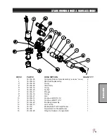
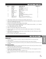
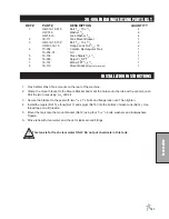
HOSE REEL MOUNT PARTS LIST
REF# PART#
DESCRIPTION
QUANTITY
1
15-749
Hose Barb
3
/
4
1
2 8887-110
3
/
4
" Orange PVC Hose 110"
1
18-040
Hose Clamp
2
3
16-129
Manual Rewind Hose Reel
1
4 HB-516-18-100 Bolt
5
/
16
-18 x 1
4
HW-516
Washer
5
/
16
4
HNTL-516-18
Lock Nut
5
/
16
- 18
4
5
16-295
Hose Fitting
3
/
4
1
6
30-110
Hose Reel Mount bracket
(part of 30-005-K)
1
7
18-249
Barb Fitting
1
8 HB-516-18-175 Bolt,
5
/
16
-18 x 1
3
/
4
(part of 30-005-K)
4
HNFL-516-18
Flange Lock Nut,
5
/
16
- 18
(part of 30-005-K)
4
1. Wear protective clothing when draining the tank and taking apart the lines.
2. Drain tank and spray system in a safe and approved method insuring that no chemical or water remain
in tank as you will be taking apart lines.
3. Remove key from ignition, set park brake and block wheels.
4. Put hose reel on hose reel bracket with fitting to the rear of machine. Use four bolts
5
/
16
- 18 x 1
and four
5
/
16
- 18 lock nuts to hold in place. Tighten bolts.
5. Put 18-249 barb fitting into hose reel side.
6. Place the 16-295 Hose Fitting into the Hose reel center.
7. Remove the blank cover from the ball valve by the manifold valve and place the 15-749 Hose Barb.
Tighten clamp.
8. Route hose from the hose barb on the ball valve to the barb fitting on the side of the hose reel. Hold in
place with the two 18-040 clamps.
9. Be sure all clamps and hardware are tight before using.
HOSE REEL ADJUSTMENTS
OPERATIONAL CHECK:
1. Pull hose off drum at least one full revolution. A clicking noise should be heard from locking mechanism.
2. Let the hose retract.
3. Pull the hose off until the first click is heard. Drum should lock when the hose tension is removed.
4. Continue pulling the hose, no more than one revolution, until no clicking is heard. Hose should rewind when tension
is removed.
HOSE REPLACEMENT PROCEDURE:
1. Facing swivel, turn the hose drum clockwise until all of the hose is removed from the drum and the drum is held by
locking mechanism. Make sure spring is locked.
2. Remove hose clamps and disconnect hose from swivel. Remove old hose.
3. Insert new hose through roller guide, connect to swivel and reinstall hose clamps. Use spring guard over hose to
protect the hose from being cut by the drum.
4. Remove check ball from old hose and install on replacement hose.
5. Carefully, keeping the tension on the hose, pull the hose to release the locking mechanism. Let the hose wind on
the drum.
Summary of Contents for Spray Star 3180
Page 11: ...9 Service END USER SERVICE CHART Duplicate this page for routine use...
Page 13: ...11 Service NOTES E...
Page 18: ...16 Diagrams BODY FRAME DRAWING...
Page 20: ...18 Parts NOSE CONE DRAWING...
Page 22: ...20 Parts NOSE CONE DRAWING...
Page 24: ...22 Parts LINKAGE DRAWING...
Page 26: ...24 Parts FRONT AXLE DRAWING...
Page 28: ...26 Parts OIL AND FUEL TANK DRAWING...
Page 30: ...28 Parts SEAT PANEL DRAWING...
Page 32: ...30 Parts ENGINE AND PUMPS DRAWING...
Page 34: ...32 Parts ENGINE AND PUMPS DRAWING...
Page 36: ...34 Parts COOLER AND EXHAUST DRAWING...
Page 38: ...36 Parts TANK DRAWING...
Page 40: ...38 Parts TURBO QUAD AGITATOR DRAWING...
Page 42: ...40 Parts 15 301 ORBITROL DRAWING...
Page 44: ...42 Parts 16 998 HYPRO PUMP DRAWING...
Page 46: ...44 Parts 30 102 EATON PUMP DRAWING...
Page 48: ...46 Parts 30 102 EATON PUMP DRAWING...
Page 50: ...48 Parts 30 101 EATON MOTOR DRAWING...
Page 52: ...50 Parts 76 197 EATON GEAR PUMP DRAWING...
Page 54: ...52 Accessories 3182 PLUMBING DRAWING RAVEN 440...
Page 56: ...54 Accessories 3184 PLUMBING DRAWING RAVEN 203...
Page 58: ...56 Accessories 3185 3186 PLUMBING DRAWING ENVIZIO PRO II SHARP SHOOTER...
Page 60: ...58 Accessories 3187 3188 PLUMBING DRAWING RAVEN 400 SHARPSHOOTER...
Page 62: ...60 Accessories 3187 3188 PLUMBING DRAWING RAVEN 400 SHARPSHOOTER...
Page 64: ...62 Accessories CONTROLS 3182 SYSTEM DRAWING RAVEN 440...
Page 66: ...64 Accessories CONTROLS 3184 SYSTEM DRAWING RAVEN 203...
Page 68: ...66 Accessories WIRING 3185 3186 SYSTEM ENVIZIO PRO II SHARP SHOOTER...
Page 70: ...68 Accessories WIRING 3187 3188 SYSTEM RAVEN 440 SHARP SHOOTER...
Page 74: ...72 Accessories 15 743 MANIFOLD VALVE DRAWING...
Page 76: ...74 Accessories 17 580 20 HEAVY BOOM...
Page 78: ...76 Accessories 17 580 20 BOOM DRAWING...
Page 80: ...78 Accessories 17 585 18 HEAVY BOOM...
Page 82: ...80 Accessories 17 585 18 HEAVY BOOM...
Page 86: ...84 Accessories 30 010 ELECTRIC HOSE REEL DRAWING...
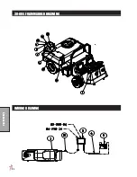
Page 90: ...88 Accessories HOSE REEL MOUNT DRAWING...
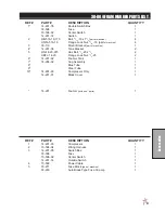
Page 92: ...90 Accessories 30 004 FOAM MARKER DRAWING WIRING DRAWING...
Page 94: ...92 Accessories 30 004 FOAM MARKER DRAWING...
Page 96: ...94 Accessories FOAMER NOZZLE MOUNT HOSE GUARD MOUNT DRAWING...
Page 99: ...97 Accessories NOTES...
Page 102: ...100 Accessories 30 006 FRESH WATER TANK DRAWING...
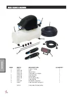
Page 106: ...104 Accessories 15 620 CHEMICAL CLEAN LOAD PARTS DRAWING...

