background image

Product Support:

Hwy SS & Poplar Ave; Cameron WI 54822
1-800-891-9435      productsupport

@

smithco.com

Parts & Service

TCV 5000

Super Truck


Turf  Care Vehicle

Model 31-000

SN: DT310001

June 2009

Revised Jan 2010

Operators

Summary of Contents for TCV 5000

Page 1: ...uct Support Hwy SS Poplar Ave Cameron WI 54822 1 800 891 9435 productsupport smithco com Parts Service TCV 5000 Super Truck Turf Care Vehicle Model 31 000 SN DT310001 June 2009 Revised Jan 2010 Operat...

Page 2: ...12 Storage 14 15 Diagrams 16 19 Wiring Diagram 16 17 Hydraulic Diagram 18 19 Parts 20 47 Body and Frame 20 21 Nose Cone 22 23 Front Axle 24 25 Oil and Fuel Tank 26 27 Seat Panel 28 29 Engine and Pump...

Page 3: ...enance instructions Failure to do so could result in personal injury or equipment damage Keep manuals in a safe place after operator and maintenance personnel have read them Right and left sides are f...

Page 4: ...ng the engine 12 Never use your hands to search for oil leaks Hydraulic fluid under pressure can penetrate the skin and cause serious injury 13 This machine demands your attention To prevent loss of c...

Page 5: ...pm or 0 0015 wt Cooling System Liquid Cooled Lubrication System Full Pressure Alternator 15Amp WHEELS TIRE Front Two 20 x 11 00 x 10 Turf 20 psi 1 4 bar Rear Two 29 x 14 00 x 15 Multi Trac 30 psi 2 0...

Page 6: ...ll fuel tank while engine is running or an enclosed area fumes are explosive and dangerous to inhale DO NOT SMOKE while filling the fuel tank DO NOT OVER FILL 5 Machine should be greased before starti...

Page 7: ...is used to regulate engine speed X TOWING When it is necessary to move the dump truck without the engine running there are 2 things that need to be done First the bypass valve built into hydrostatic...

Page 8: ...ghten or replace as needed 5 Inspect hydraulic lines for damage or leaks Never use hands to inspect for leaks 6 Check the hydraulic fluid level The hydraulic fluid tank is located under the seat The f...

Page 9: ...Wear eye protection and rubber gloves 3 Avoid breathing fumes when electrolyte is added 4 Avoid spilling or dripping electrolyte Battery Electrolyte is an acidic solution and should be handled with ca...

Page 10: ...the air cleaner on this engine is a dry type never apply oil to it 1 Open evacuator valve see engine manual once a week to remove large particles of dust and dirt 2 Wipe the inside of the air cleaner...

Page 11: ...achine for a few minutes Check oil level and for leaks 5 Always use extreme caution when filling hydraulic oil tank or checking level to keep system free of contaminants Check and service more frequen...

Page 12: ...vel on the shift arm that is required for the light to remain on The light must be on ONLY with the shift arm centered TOWING When it is necessary to move the dump truck without the engine running the...

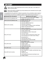
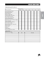
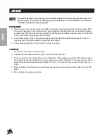
Page 13: ...11 Service NOTES...

Page 14: ...ter Change oil filter Change hydraulic filter Clean battery terminals Every 400 hours Replace Fuel Filter Lubricate machine Visual inspection of machine and hydraulic hoses Change oil Torque lug nuts...

Page 15: ...ne cooling fins Check for unusual engine noises Check the hydraulic oil level Check hydraulic hoses and fittings for damage Check for fluid leaks Check the tire pressure 20 30 psi Check the Instrument...

Page 16: ...Leave spark plugs in holes or seal spark plug holes with suitable threaded metal plugs and cover all openings into engine with suitable non hygroscopic material 3 Check coolant protection Store machin...

Page 17: ...ings in engine and accessories with non hygroscopic material Mask off all areas to be used for electrical contact 10 Tape all openings and make sure all surfaces are dry Then spray all taped openings...

Page 18: ...16 Diagrams WIRINGDIAGRAM Color Code Chart Bl Blue Br Brown Y Yellow G Green O Orange R Red B Black P Purple W White...

Page 19: ...292 Seat Switch 1 6 13 488 Ignition Switch 1 7 17 524 Lights 2 10 421 Pigtail 2 8 15 725 Mount Panel End 1 15 727 Switch Actuator 1 15 782 Rocker Switch Unlit 1 9 48 147 Ground Battery Cable 1 10 33...

Page 20: ...18 Diagrams HYDRAULICDIAGRAM Use dielectric grease on all electrical connections Letter Code Chart C Center I Inside O Outside T Top B Bottom...

Page 21: ...Hydraulic Hose 1 14 30 085 Hydraulic Hose 1 15 30 090 Hydraulic Hose 2 16 30 087 Hydraulic Hose 2 17 30 099 Wheel Drive 2 18 30 100 Hydraulic Release Brakes 2 19 30 101 Eaton Wheel Motors 2 20 30 089...

Page 22: ...20 Diagrams BODY FRAMEDRAWING...

Page 23: ...nder 1 9 15 822 Nose Cone Fiberglass 1 50 400 Rubber Grommet 1 10 31 025 Main Frame 1 11 17 524 Oval Light 2 10 421 Pigtail 2 12 30 065 Front Panel 1 27 055 Flush Hinge 1 13 15 752 Left Step 1 15 751...

Page 24: ...22 Parts NOSE CONE DRAWING...

Page 25: ...l Blanks 4 31 026 Decal Dashboard 1 18 15 725 Mount Panel End 1 15 727 Switch Actuator 1 15 782 Rocker Switch Unlit 1 19 HSM 10 32 100 Machine Screw 10 32 x 1 6 HWLM 6 Lock Washer 6 6 HNFL 10 32 Flang...

Page 26: ...24 Parts FRONTAXLEDRAWING...

Page 27: ...HCP 58 175 Clevis Pin 5 8 x 13 4 1 HP 18 100 Cotter Pin 1 8 x 1 1 12 75 714 Hydraulic Cylinder 1 14 254 Seal Kit 1 13 18 154 Rod End 3 HG 14 28 90 Grease Fitting 1 4 28 x 90 3 14 HB 58 11 250 Bolt 5...

Page 28: ...26 Parts OIL AND FUEL TANK DRAWING...

Page 29: ...Flange Lock Nut 1 4 20 4 9 26 054 Bushing Insert 1 10 26 055 Shut Off Valve 1 11 18 397 90 Hose Barb Fitting 3 12 18 407 5 8 45 Hose Barb Fitting 1 13 18 399 Tee 1 14 18 400 Pipe Nipple 1 15 18 250 B...

Page 30: ...28 Parts SEAT PANEL DRAWING...

Page 31: ...wer Hood Bracket 1 12 30 030 Roll Bar 1 HB 12 13 200 Hex Bolt 1 2 13 x 2 8 HW 12 Flat Washer 1 2 16 HNTL 12 13 Lock Nut 1 2 13 8 13 30 055 Upper Hood Bracket 1 14 30 057 Hood Rod 1 HP 18 075 Cotter Pi...

Page 32: ...30 Parts ENGINE AND PUMPS DRAWING...

Page 33: ...mp 1 30 098 01 Seal Kit 1 18 30 029 Centering Arm Mount 1 19 30 082 Idler Arm 1 HMB 12 14 Machine Bushing 1 2 14GA HP 18 075 Cotter Pin 1 8 x 3 4 1 20 18 404 Adapter 1 21 18 405 Run Tee 1 22 14 266 Ba...

Page 34: ...32 Parts COOLER AND EXHAUST DRAWING...

Page 35: ...0 105 Thermal Transfer Heat Exchanger 1 13 18 107 Pipe Thread Reducer 1 14 18 402 3 4 x 90 Hose Barb 1 15 Radiator 1 16 18 408 Tube End Reducer 1 17 18 397 90 Hose Barb 1 18 30 042 Kubota 33 5 HP Dies...

Page 36: ...34 Parts 31 015 GONDOLA DUMP BOX DRAWING...

Page 37: ...38 16 300 Bolt 3 8 16 x 3 4 HNTL 38 16 Lock Nut 3 8 16 4 5 31 025 Main Frame 1 6 72 040 Hydraulic Cylinder 1 72 040 01 Seal Kit 1 23 184 Fitting 2 7 72 040 02 Clip and Pin come with cylinder 2 8 31 01...

Page 38: ...36 Parts 31 028 CARGO TAILGATE BOX DRAWING...

Page 39: ...6 x 3 4 HNTL 38 16 Lock Nut 3 8 16 4 5 31 025 Main Frame 1 6 72 040 Hydraulic Cylinder 1 72 040 01 Seal Kit 1 23 184 Fitting 2 7 72 040 02 Clip and Pin come with cylinder 2 8 31 031 Dump Guard Hinge 3...

Page 40: ...38 Parts 13 731 SINGLE BANK HYDRAULIC VALVE DRAWING...

Page 41: ...5 78 415 04 Flanged Washer HDM10 3 6 13 731 03 Spool 1 7 78 415 11 Positioner 1 8 78 415 08 Plug 3 9 78 415 09 Lever Group HDS11 3 10 78 415 10 Metric Socket Screw M5 x 8 x 45 2 11 13 731 04 1 4 Ball...

Page 42: ...40 Parts 15 301 ORBITROL DRAWING...

Page 43: ...16 15 301 05 Spacer 1 17 15 301 04 Gerotor 1 18 O Ring 1 19 Seal 1 20 15 301 03 End Cap 1 21 15 301 02 Cap Screw 7 15 301 01 Seal Kit 15 301 ORBITOR SPECIFICATIONS Maximum System Pressure 1015 psi 70...

Page 44: ...42 Parts 30 102 EATON PUMP DRAWING...

Page 45: ...1 O Ring 1 19 Retaining Ring 1 20 33 058 41 Dump Valve Actuator 1 21 Quad Ring 1 22 33 058 34 Key 1 23 Seal Sub Assembly 2 24 33 058 32 Plug S A 2 O Ring 2 25 33 058 19 Plug Sub Assembly 1 O Ring 1 26...

Page 46: ...44 Parts 30 102 EATON PUMP DRAWING...

Page 47: ...1 49 Retaining Ring 2 50 33 058 10 Thrust Race 2 51 33 058 11 Thrust Bearing 1 52 33 058 31 Washer 1 53 33 058 52 Shaft Seal 1 54 Retaining Ring 1 55 33 058 28 Drive Shaft 1 56 33 058 17 Housing Asse...

Page 48: ...46 Parts 30 101 EATON MOTOR DRAWING...

Page 49: ...7 Shaft Face Seal 1 8 30 101 03 Wear Plate 1 9 30 101 04 Main Drive 1 10 30 101 05 Geroler 1 11 30 101 06 Valve Plate 1 12 14 207 Valve Drive 1 13 14 208 Valve 1 14 30 101 07 Balance Ring 1 15 14 210...

Page 50: ...Sides of Seat Panel 25 298 Decal Warning Hot Cooler Guard Above Muffel on Tank Side Panel Behind Seat 25 321 Decal Refuel w Diesel Front Right Tank 25 356 Decal Tire Pressure 20psi Front Tires 25 371...

Page 51: ...ACEMENTBELTS SEAL KITS 15 301 Power Steering Orbital Motor 15 301 01 Seal Kit 30 101 Wheel Motors 30 101 11 Seal Kit 30 102 Hydrostatic Pump 33 058 01 Seal Kit 30 098 Gear Pump 30 098 01 Seal Kit 72 0...

Page 52: ...you need help locating an Authorized Smithco Distributor or if you have questions regarding your warranty rights or responsibilities you may contact us at Smithco Product Support Department 200 W Pop...

Page 53: ...warranty gives you specific legal rights and you may also have other rights which vary from state to state THEREARE NO OTHER EXPRESS WARRANTIES OTHER THAN THOSE SET FORTHABOVE ALLIMPLIED WARRANTIES O...

Reviews: