HOT LINE
®
Blood and Fluid Warmer
Technical Service Pack
19
S E C T I O N 3
T e c h n i c a l D e s c r i p t i o n
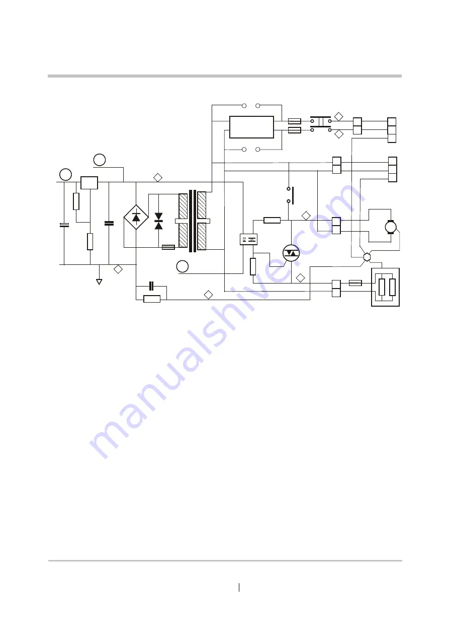
Electrical Power Circuits
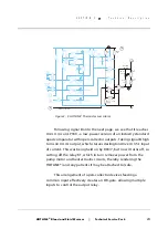
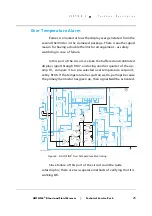
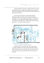
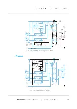
Power circuitry is conventional, and is constructed on the PCB.
There are three fuses, F1 and F2 (both 1.5A) for the Mains input, and
F3 (375 mA) for the low voltage circuits. F3 is wire-ended device,
soldered into place at the top edge of the PCB.
On the Mains side, the power normally passes through a line
filter to reduce susceptibility to interference (this filter is not always
required for domestic US units.) The pump motor is switched by a
PCB-mounted relay K1, and the heater element is controlled by a
triac. The heater can only be energised when the pump is powered
on, since without recirculating solution flow, the heater element
would quickly overheat.
The heater triac is triggered via an optical isolator, and all the
Mains voltage circuits are physically distanced from the low-voltage
circuits for safety reasons. The low-voltage control circuits are
13
U501
U1
+
CR1
F3 375mA
7
9
10
12
1
R502
3.16k
C 2
220F
µ
C501
10F
µ
R501
453R
T1
F1 1.5A
SW1
DPST
Thermofuse
56 C
o
F2 1.5A
R4
1k
J7
L
N
E
J6
U2
TRIAC
R3
270R
U3
OPTO
K1
Contacts
2
4
6
8
1
3
5
7
TB1
TB1
Earth Stud
Water
Heater
Pump
Motor
AUX
Outlet
TB1
TB1
Line
Input
J10
1
3
4
6
MT2
6
4
Gate
1
2
MT1
C
VU
10
38
30
22
26
LF1
Filter
14
R502
3.16k
C100
100pF
GM-HL90_8A103
Figure 3 - 1: HOTLINE
®
Power Circuits
Summary of Contents for level 1 HOTLINE HL-90
Page 1: ......
Page 14: ...Introduction Specifications Blood and Fluid Warmer ...
Page 20: ...Sub Assemblies Blood and Fluid Warmer ...
Page 28: ...Technical Description Blood and Fluid Warmer ...
Page 45: ...Disassembly Procedures Blood and Fluid Warmer ...
Page 58: ...Blood and Fluid Warmer Maintenance Testing and Calibration ...
Page 83: ...Troubleshooting Blood and Fluid Warmer ...
Page 88: ...Spare Parts Blood and Fluid Warmer ...
Page 96: ...Rounding Off Blood and Fluid Warmer ...
Page 106: ...Appendix 1 Circuits Blood and Fluid Warmer ...
Page 110: ...Appendix 2 PCB Layout Blood and Fluid Warmer ...
Page 115: ...Appendix 3 Symbols Glossary Blood and Fluid Warmer ...
Page 118: ...Appendix 4 Frequently Asked Questions Information Bulletins Blood and Fluid Warmer ...
Page 132: ...Ndjg CdiZh 9 V gVbh ...


