HOT LINE
®
Blood and Fluid Warmer
Technical Service Pack
21
S E C T I O N 3
T e c h n i c a l D e s c r i p t i o n
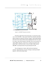
As a result, the current through the chain
[control thermistor -
R202 - R01/9]
is roughly proportional to the recirculating solution
temperature, and thus, so is the voltage sample at R202 slider. This
is buffered by U2.1, part of an LP324N quad op-amp, and passed to
U2.2, which is configured as a comparator. At pin 5 of U2.2, a
reference voltage of about 5 volts is created by the voltage divider
resistors R03/8 and R01/8.
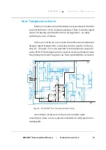
If the temperature-dependent sample at pin 6 is less than the
reference level set at pin 5, then pin 7 will go high, which switches
on the darlington driver U3.1, and so turning on the opto/triac/
heater combination. However, this also grounds R207 via CR201,
which starts discharging C201, and so reducing the reference
voltage at U2.2/5. Unless the recirculating solution is very cold, the
reference voltage will soon dip below the sample voltage, so
turning off the heater circuit.
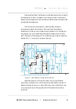
As soon as U3.1 turns off, C201 can start recharging to 5 volts,
and at some point the reference voltage overtakes the sample
voltage, and the heater turns on again, repeating the cycle. R204
provides a modest amout of positive feedback, ensuring that the
switch transitions are snap-action.
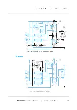
You can see that the repetition rate of the circuit depends both
on the RC time constants around C201, and also on the temperature
of the recirculating solution in the reservoir. If this is still some
distance from the desired temperature, the sampled voltage will
“sag” very quickly when the heater turns off, and fresh cold
recirculating solution is pumped through the heater unit.
If, however, the HOTLINE
®
has been running some while, all the
recirculating solution in the circulation loop will be at, or close to,
the desired temperature, so the sample voltage will hardly move at
all.
Summary of Contents for level 1 HOTLINE HL-90
Page 1: ......
Page 14: ...Introduction Specifications Blood and Fluid Warmer ...
Page 20: ...Sub Assemblies Blood and Fluid Warmer ...
Page 28: ...Technical Description Blood and Fluid Warmer ...
Page 45: ...Disassembly Procedures Blood and Fluid Warmer ...
Page 58: ...Blood and Fluid Warmer Maintenance Testing and Calibration ...
Page 83: ...Troubleshooting Blood and Fluid Warmer ...
Page 88: ...Spare Parts Blood and Fluid Warmer ...
Page 96: ...Rounding Off Blood and Fluid Warmer ...
Page 106: ...Appendix 1 Circuits Blood and Fluid Warmer ...
Page 110: ...Appendix 2 PCB Layout Blood and Fluid Warmer ...
Page 115: ...Appendix 3 Symbols Glossary Blood and Fluid Warmer ...
Page 118: ...Appendix 4 Frequently Asked Questions Information Bulletins Blood and Fluid Warmer ...
Page 132: ...Ndjg CdiZh 9 V gVbh ...


