HOT LINE
®
Blood and Fluid Warmer
Technical Service Pack
40
S E C T I O N 4
D i s a s s e m b l y
Step 3: Release the Earth Stud
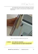
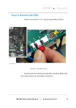
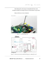
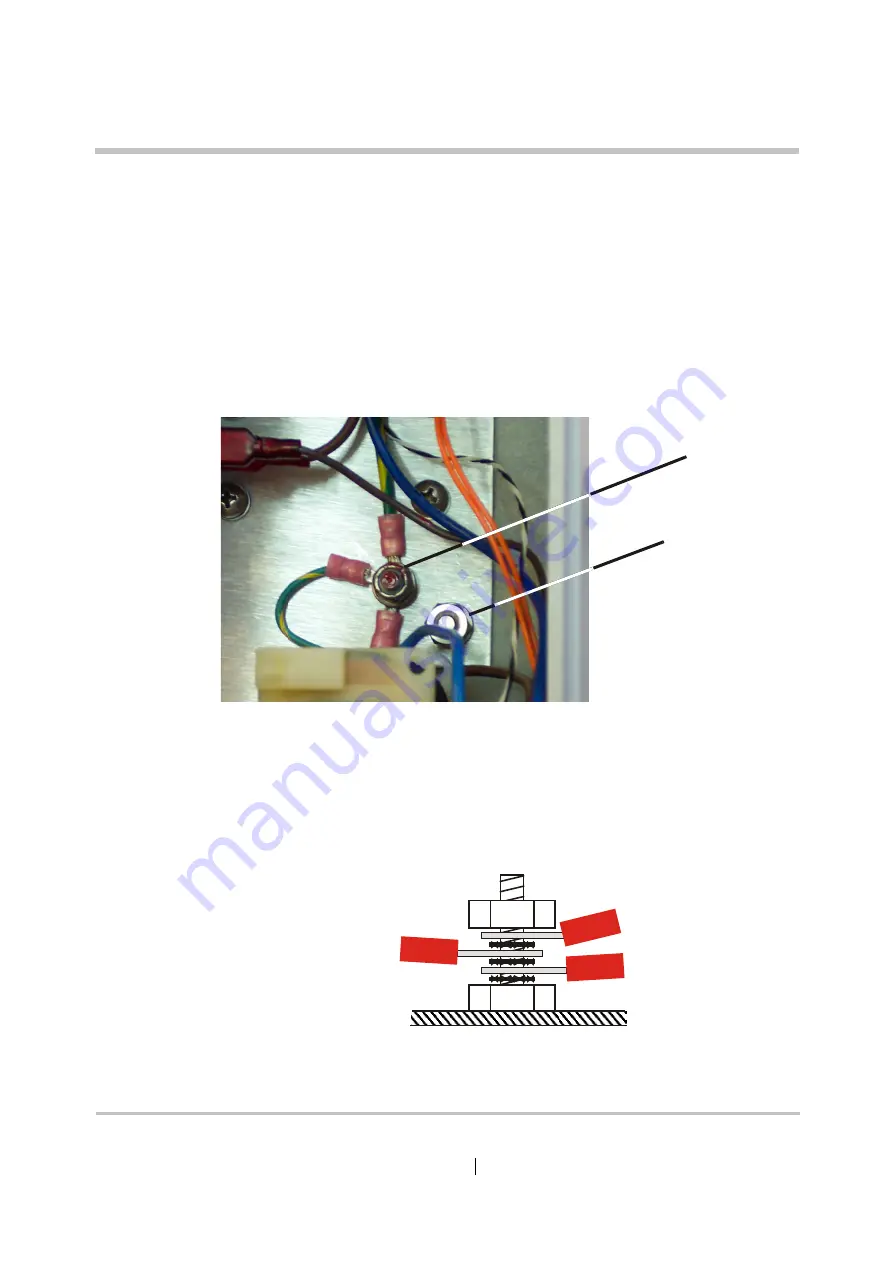
With the PCB removed, you will be able to see the external
Earthing Stud which is attached to the chassis and passes out
through the rear of the case. Undo the 10mm nut holding it in place,
using a spanner on the outside to prevent rotation. Undo the 3/8
inch nut and take off the earth conductors from the internal Earth-
ing Star Point.
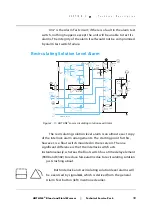
Notice the order of assembly on this terminal: the crinkle
washers are not there just to prevent unscheduled vibrational dis-
assembly, but also to cut into any corrosion on the ring termina-
tions and ensure good continuity.
External
Earthing Stud
Internal
Earthing
Star Point
GM-0163_8415-GB-A
Figure 4 - 9: Earthing Arrangements
Figure 4 - 10: Use of Crinkle Washers
Summary of Contents for level 1 HOTLINE HL-90
Page 1: ......
Page 14: ...Introduction Specifications Blood and Fluid Warmer ...
Page 20: ...Sub Assemblies Blood and Fluid Warmer ...
Page 28: ...Technical Description Blood and Fluid Warmer ...
Page 45: ...Disassembly Procedures Blood and Fluid Warmer ...
Page 58: ...Blood and Fluid Warmer Maintenance Testing and Calibration ...
Page 83: ...Troubleshooting Blood and Fluid Warmer ...
Page 88: ...Spare Parts Blood and Fluid Warmer ...
Page 96: ...Rounding Off Blood and Fluid Warmer ...
Page 106: ...Appendix 1 Circuits Blood and Fluid Warmer ...
Page 110: ...Appendix 2 PCB Layout Blood and Fluid Warmer ...
Page 115: ...Appendix 3 Symbols Glossary Blood and Fluid Warmer ...
Page 118: ...Appendix 4 Frequently Asked Questions Information Bulletins Blood and Fluid Warmer ...
Page 132: ...Ndjg CdiZh 9 V gVbh ...

