background image

 HOT LINE

®

  Blood and Fluid  Warmer

Technical Service  Pack

50

S E C T I O N   5    


E v e r y   1 2   M o n t h s

Over Temperature Alarm Test 

Allow the unit to run for sufficient time to stabilise the 

temperature. Press and hold the Over Temperature Alarm Test 
button.  Observe:

 the DISPLAY rises to 43°C - 44°C .

 the GREEN LED extinguishes.

 the RED Over Temperature LED lights up.

 the AUDIBLE ALARM commences beeping.

 the RECIRCULATING SOLUTION ceases circulating. 

If any of the above responses are missing, the unit must be 

removed from service and repaired. 

Recirculating Solution Level Alarm

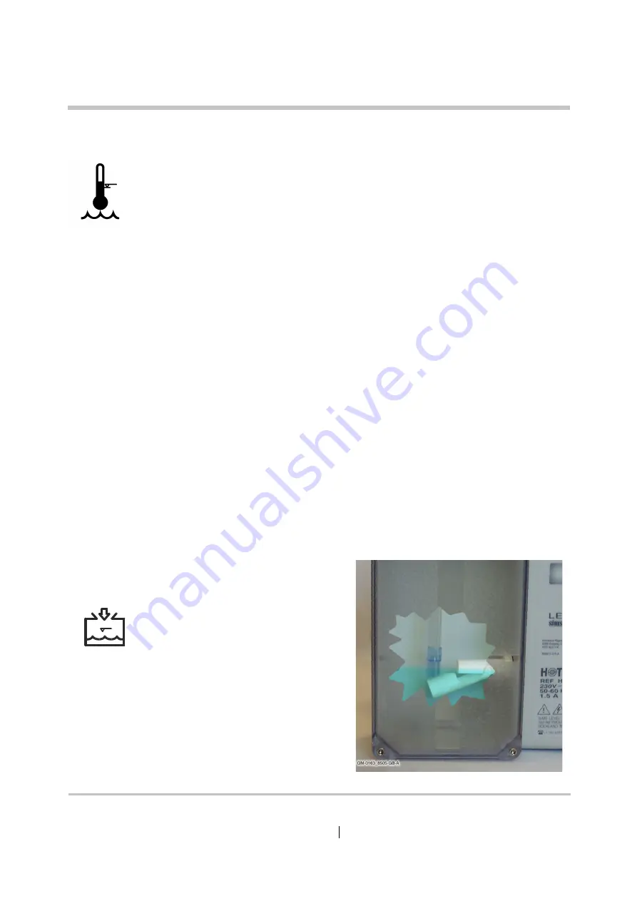
Remove the Fill Port plug. Using a non-magnetic tool, gently 

depress the float switch arm. 

Figure 5 - 1:  Depressing the float 

switch. Here you see an offcut of 
scrap Disposable Set performing 

excellently as a non-magnetic probe. 

Summary of Contents for level 1 HOTLINE HL-90

Page 1: ......

Page 2: ...mblies Disassembly Procedures Spare Parts Troubleshooting Rounding Off Appendix 1 Circuits Appendix 2 PCB Layout Appendix 3 Symbols Glossary Appendix 4 Frequently Asked Questions Information Bulletins Blood and Fluid Warmer Maintenance Testing and Calibration ...

Page 3: ...s Medical is a global manufacturer and supplier of medical devices for treating critically ill patients These devices may be used in high risk situations and include ambulatory and hospital infusion pumps neo natal and paediatric monitors blood and fluid warmers and convective warming systems for patients Figure P 1 A selection of Smiths Products old and new ...

Page 4: ...low and fast flow intravenous or irrigation applications and convective hot air warming systems These products help to prevent hypothermia and maintain normothermia in patients undergoing surgery in the operating theatre recovery ward and in the casualty departments in emergency situations Why is Temperature Management important Patients undergoing surgical procedures are exposed to a variety of i...

Page 5: ... emergence from anesthesia and longer recovery room stays Increased risk of wound infection Wound infection and delayed wound healing result in longer hospital stays Wound infection can prolong hospitalization Postoperative discomfort Thermal discomfort shivering and fatigue can occur when core temperature decreases by 1 C The HOTLINE Blood and Fluid Warmer The HOTLINE Blood and Fluid Warmer uses ...

Page 6: ...istributor at USA Canada Smiths Medical ASD Inc 160 Weymouth Street Rockland MA 02370 USA USA Canada 1 800 258 5361 International 1 781 878 8011 European Representative 6PLWKV 0HGLFDO QWHUQDWLRQDO WG UREKA 0ARK OWER 0EMBERTON SHFORD ENT 4 5 5HJLVWHUHG LQ QJODQG 1XPEHU 7HO Australian Representative Smiths Medical Australasia Pty Ltd 61 Brandl Street Brisbane Technology Park Eight Mile Plains QLD 41...

Page 7: ...d in a format that permits users to access the text and illustrations for their own use e g training and educational purposes Smiths Medical cannot be held responsible for the accuracy of nor any resulting incident arising from information that has been extracted from this publication and compiled into the user s documentation Other than as herein noted no part of this publication may be reproduce...

Page 8: ...Service Pack vi P R E F A C E É R e v i s i o n H i s t o r y Revision History Issue No Reason for Change Pages Affected Date 000 New Revision First Release All July 2006 001 Updated EU Rep address iv v vi 6 front and back covers October 2011 ...

Page 9: ... i m s Aims To provide technical engineering support staff with the practical and theoretical knowledge necessary to diagnose maintain repair and update Smiths Medical products as appropriate to meet the needs of your healthcare establishment s equipment management protocols ...

Page 10: ...ient Successful training course attendees may be certified by Smiths Medical an option not open to non attendees Please contact your local Smiths Medical distributor for more details We strongly recommend course attendance wherever possible to ensure the highest standards of maintenance for your HOTLINE units On completion of the program delegates will have knowledge of the following General funct...

Page 11: ...neous 5 Contra Indications 6 Section 2 Sub assemblies Enclosure 9 11 Recirculating Solution Path 12 Interlock Block 13 PCB Mounting 14 Section 3 Technical Description General 16 Mechanical 16 Controls and Indicators 17 Side Panel 17 Electrical 19 Power Circuits 19 Control Circuit 20 Digital Display 22 Thermistor Loss 23 Over Temperature Alarm 25 Flasher 27 Interlock Alarm 29 Recirculating Solution...

Page 12: ...ery 30 days 48 Every 12 months 49 Maintenance Solutions 54 Changing the Recirculating Solution 54 Sterile Distilled Water 54 Isopropyl Alcohol Solution 56 Hydrogen Peroxide Solution 57 Routine Maintenance Checklists 60 Full Service Test Procedure 64 Things you will need 64 HL 90 Service Test Specification 65 Section 6 Troubleshooting Troubleshooting Hints 71 Over Temperature Alarm always ON 71 Ove...

Page 13: ...ssories 79 Water pump and related parts 79 Interlock Block and related parts 80 External Parts Rear of case 81 Poleclamp parts 82 Section 8 Rounding Off Updates 84 Modifications 84 GRI Pump 86 Float Switch Sealing Washer 87 Appendix 1 Circuits Appendix 2 PCB Layout PCB layout A2 2 Component Listing A2 3 Appendix 3 Symbols Glossary Appendix 4 Customer Information Bulletins HOTLINE Frequently Asked ...

Page 14: ...Introduction Specifications Blood and Fluid Warmer ...

Page 15: ... IV line with a layer of precisely controlled warmed recirculating solution HOTLINE provides active warming of the patient line all the way down to the patient connec tion thus eliminating patient line cool down Superior Performance The HOTLINE innovative tubing design eliminates patient line cool down and delivers warm intravenous fluids to pa tients Ease of Use Simple 1 step plug in disposable f...

Page 16: ...o 4750 ml hr Digital display of recirculating solution temperature Electronic circuitry continuously monitors recirculating solu tion temperature Green Warming operating LED Red fault indicator LEDs identify 3 common fault conditions Audible alarm indication Alarm test facility Temperature Display Operating LED Disposable Interlock Recirculating Solution Level Over Temperature GM 0163 8102 GB A Fa...

Page 17: ... 8 3 21 0 Width 7 0 17 8 Weights lbs kg Weight dry 7 6 3 5 Weight full 11 0 5 0 Weight as Shipped 7 95 3 6 Electrical HL 90 US HL 90 UK Supply Voltage 115 V AC 230 V AC Supply Current 3 0 A 1 5 A Supply Frequency 50 60 Hz 50 60 Hz Classification Class 1 Class 1 Safety Rating Type BF applied part Type BF applied part Power Cord 0 75mm x 3 6 m 0 75mm x 3 6 m ...

Page 18: ...nce Enclosure Protection IEC 60529 IP Code IPX1 Miscellaneous Standards Compliance Fluid Warmers ASTM F2172 02 Product Safety EN60601 1 UL2601 1 EMC EN60601 1 2 FCC 47 CFR part 15 Class B Performance Recirculating Solution temperature display will reach 37o C from ambient in about 4 minutes Operating Temp Set Point 41 5o C 0 5o C Over Temp Set Point 42 6o C 0 5o C Max Height on IV pole 107 cm 42 i...

Page 19: ... I O N 1 C o n t r a i n d i c a t i o n s Contra indications Not Suitable for use in the presence of flammable anaesthetic mixtures with air or oxygen or with nitrous oxide HOTLINE disposables are not suitable for use with pressure devices generating over 300 mmHg ...

Page 20: ...Sub Assemblies Blood and Fluid Warmer ...

Page 21: ...C T I O N 2 S u b a s s e m b l i e s Sub assemblies The principal sub assemblies to be found in the HOTLINE HL 90 are The enclosure and chassis parts The recirculating solution path components The PCB and its mountings These are detailed on the following pages ...

Page 22: ...HOTLINE Blood and Fluid Warmer Technical Service Pack 9 S E C T I O N 2 E n c l o s u r e 1 Enclosure 1 ...

Page 23: ...HOTLINE Blood and Fluid Warmer Technical Service Pack 10 S E C T I O N 2 E n c l o s u r e 2 Enclosure 2 Newer design Fillport Cover removes need for chain or retaining screw ...

Page 24: ...HOTLINE Blood and Fluid Warmer Technical Service Pack 11 S E C T I O N 2 E n c l o s u r e 3 Enclosure 3 ...

Page 25: ...HOTLINE Blood and Fluid Warmer Technical Service Pack 12 S E C T I O N 2 R e c i r c u l a t i n g S o l u t i o n P a t h Recirculating Solution Path ...

Page 26: ...HOTLINE Blood and Fluid Warmer Technical Service Pack 13 S E C T I O N 2 I n t e r l o c k B l o c k Interlock Block ...

Page 27: ...HOTLINE Blood and Fluid Warmer Technical Service Pack 14 S E C T I O N 2 P C B M o u n t i n g PCB Mounting ...

Page 28: ...Technical Description Blood and Fluid Warmer ...

Page 29: ... solution if the temperature reaches 43o C The heater current is supplied via a thermal cutout so in the case of a circulation failure the heater will be protected against burn out the same cutout will act in the event of catastrophic breakdown of components in the HOTLINE circuitry that prevents the alarm state from disengaging the heater These three levels of safety ensure that the IV Fluid in t...

Page 30: ...t is not fitted properly Reattach the Warming Set and continue This flashing RED indicator with audible alarm shows that warming and circulating has stopped because there is not enough recirculating solution in the unit to operate the float switch Refill and continue This flashing RED indicator with alarm shows that warming and circulating has been stopped because the recirculating solution reache...

Page 31: ...n from room temperature to 37oC in 4 minutes In the horizontal leg of the heater assembly a special dual thermistor unit is submerged in the flow to monitor and control the warmed recirculating solution temperature Clamped to the external surface of the heater assembly is the T Stat a thermally operated bi metallic cutout that breaks the circuit at temperatures above 50o C The cutout only self res...

Page 32: ...nd the heater element is controlled by a triac The heater can only be energised when the pump is powered on since without recirculating solution flow the heater element would quickly overheat The heater triac is triggered via an optical isolator and all the Mains voltage circuits are physically distanced from the low voltage circuits for safety reasons The low voltage control circuits are 13 U501 ...

Page 33: ...l operating temperatures the thermistors each have a resistance of about 15k and this decreases roughly linearly with increasing temperature Q1 78L05 LCD Module Alarm Test O temp Test Control Sensor Display Sensor U1 4 U1 1 U1 2 J4 J1 U3 1 U2 2 U2 3 J201 U3 7 10 1 2 3 4 5 6 7 8 9 10 11 12 13 t t 1 1 2 2 3 3 4 4 U3 6 VU C S AA X 5 8 4 11 9 6 10 7 R202 5k Heat Control R203 154k R108 10M R03 5 15k OT...

Page 34: ...eference voltage at U2 2 5 Unless the recirculating solution is very cold the reference voltage will soon dip below the sample voltage so turning off the heater circuit As soon as U3 1 turns off C201 can start recharging to 5 volts and at some point the reference voltage overtakes the sample voltage and the heater turns on again repeating the cycle R204 provides a modest amout of positive feedback...

Page 35: ...d presented to the digital LCD millivolt meter module for display The window in the front case allows two digits to be seen by the user although the third digit tenths of a degree may be seen by the technician when the case front is removed Q1 78L05 LCD Module Alarm Test O temp Test Control Sensor Display Sensor U1 4 U1 1 U1 2 J4 J1 U3 1 U2 2 U2 3 J201 U3 7 10 1 2 3 4 5 6 7 8 9 10 11 12 13 t t 1 1...

Page 36: ...istance of some 150K or more then U2 3 will turn on sending signal X high Needless to say there is no place on earth cold enough to get this much resistance from the thermistor through natural causes Q1 78L05 LCD Module Alarm Test O temp Test Control Sensor Display Sensor U1 4 U1 1 U1 2 J4 J1 U3 1 U2 2 U2 3 J201 U3 7 10 1 2 3 4 5 6 7 8 9 10 11 12 13 t t 1 1 2 2 3 3 4 4 U3 6 VU C S AA X 5 8 4 11 9 ...

Page 37: ...by rendering the HOTLINE and any patients it may be attached to safe This arrangement of open collector devices feeding a common input effectively creates an OR gate allowing multiple inputs to control the output relay Float Switch Float System Normal Interlock Switch Interlock Overtemp J3 J2 U4 2 U4 1 U4 3 U4 4 Relay K1 U3 3 Piezo U3 2 U3 4 U3 5 U2 4 S X AA 10 VU 15 12 3 R305 100k R03 7 15k R03 1...

Page 38: ...ll be activated Since failure of this part of the circuit could be quite catastrophic there are two separate methods of verifying that it is working OK Q1 78L05 LCD Module Alarm Test O temp Test Control Sensor Display Sensor U1 4 U1 1 U1 2 J4 J1 U3 1 U2 2 U2 3 J201 U3 7 10 1 2 3 4 5 6 7 8 9 10 11 12 13 t t 1 1 2 2 3 3 4 4 U3 6 VU C S AA X 5 8 4 11 9 6 10 7 R202 5k Heat Control R203 154k R108 10M R...

Page 39: ...signal X did previously using U4 3 to cut off the pump and heater circuits In addition however there is a LED driven by U3 4 visible from the case exterior to warn the operator that this fault situation has occurred Q1 78L05 LCD Module Alarm Test O temp Test Control Sensor Display Sensor U1 4 U1 1 U1 2 J4 J1 U3 1 U2 2 U2 3 J201 U3 7 10 1 2 3 4 5 6 7 8 9 10 11 12 13 t t 1 1 2 2 3 3 4 4 U3 6 VU C S ...

Page 40: ...R401 1k C302 10 F µ C301 0 1 F µ 3 2 14 4 13 6 5 12 7 10 11 12 13 5 9 8 12 3 3 1 1 2 2 2 4 15 14 13 8 14 9 1 GM HL90_8310 A Float Switch Float System Normal Interlock Switch Interlock Overtemp J3 J2 U4 2 U4 1 U4 3 U4 4 Relay K1 U3 3 Piezo U3 2 U3 4 U3 5 U2 4 S X AA 10 VU 15 12 3 R305 100k R03 7 15k R03 1 15k R03 2 15k R302 8 2M R307 15 4k R301 722R R02 2 15k R02 3 15k R01 2 15k R03 6 15k R03 9 15k...

Page 41: ... Whenever the LED is ON the piezo sounder is powered by the volt drop across the LED s current limiting resistor R301 so it beeps in synchronism with the flashing of the alarm LED Exercise If more than one alarm happened at once then two or more LEDs would be flashed by this circuit The extra current drain should increase the volt drop across R301 so you would expect the Piezo sounder to increase ...

Page 42: ... faultfinding U03 2 is kept turned on by the pull up resistor R03 1 so that if there is a fault in the interlock switch off board wiring or the J2 connector isn t fully connected the alarm is defaulted ON You need a good continuous circuit through J2 to allow U3 7 to pull U03 2 low and turn the alarm state off Float Switch Float System Normal Interlock Switch Interlock Overtemp J3 J2 U4 2 U4 1 U4 ...

Page 43: ...hereas the float switch has a time delay element R308 and C302 to reduce false alarms due to recirculating solution just sloshing about Both interlock and recirculating solution level alarms will be exercised by signal AA which is derived from the general Alarm Test button left mentioned earlier Float Switch Float System Normal Interlock Switch Interlock Overtemp J3 J2 U4 2 U4 1 U4 3 U4 4 Relay K1...

Page 44: ... so All this current has to come from the Op amp U2 4 type number LP324N which is described by its makers as a MICROPOWER device For this reason its ability to source current is less than you might have thought You can see that from this graph Not wanting to bore you we won t figure out all the voltdrops across all the various components but you can see that if the first LED is taking 12 15 mA a r...

Page 45: ...Disassembly Procedures Blood and Fluid Warmer ...

Page 46: ...h A F Allen key hex wrench 7 8 inch A F open ended spanner wrench 3 4 inch A F open ended spanner wrench 7 16 inch A F open ended spanner wrench 3 8 inch A F deep box spanner OR socket and extension drive 1 4 inch A F open ended spanner wrench 10 mm A F open ended spanner wrench Optional Oetiker Clenching Tool This will be needed if it is intended to replace the heater ele ment or the pump motor c...

Page 47: ...the HOTLINE has been recently used be aware that some interior components may be hot Place the HOTLINE on a firm surface at a convenient height Loosen the front cover screws Early models have six screws facing forward These screws are tethered to the front panel so it is neither necessary or desirable to completely remove them Figure 4 1 The underneath view of a HOTLINE with the newer one part cas...

Page 48: ... front cover retaining screws locat ed under the unit Again it is not necessary to completely remove these screws Figure 4 2 Loosen but don t completely remove these screws WARNING STATIC SENSITIVE COMPONENTS Ensure that proper antistatic precautions are taken before attempting any procedure that requires handling the PCB ...

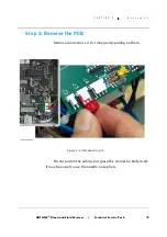
Page 49: ...k 36 S E C T I O N 4 D i s a s s e m b l y Step 2 Remove the PCB Remove connectors J2 J3 J4 by gently pulling on them Do not pull on the wiring but grasp the connector body itself It may be easier to use the needle nose pliers Figure 4 3 Disconnecting J3 ...

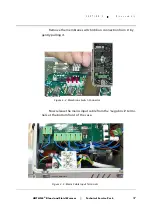
Page 50: ... 4 D i s a s s e m b l y Remove the membrane switch ribbon connection from J1 by gently pulling it Now release the mains input cable from the Lego brick termi nals at the bottom front of the case Figure 4 4 Membrane Switch Connector Figure 4 5 Mains Cable Input Terminals ...

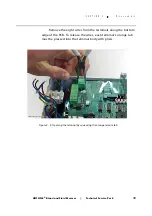
Page 51: ...O N 4 D i s a s s e m b l y Remove the eight wires from the terminals along the bottom edge of the PCB To release the wires each terminal s orange tab must be pressed into the terminal body with pliers Figure 4 6 Opening the terminal by squeezing the orange release tab ...

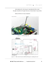
Page 52: ...tively the tabs may be manipulated with a small straight screwdriver through the slot on the terminal s top surface Remove the four screws indicated GM 0163_8408 GB A Only on older models 1 2 3 4 Figure 4 7 PCB Mounting Points Figure 4 8 Older versions have an additional fixing screw making five in all ...

Page 53: ...lace using a spanner on the outside to prevent rotation Undo the 3 8 inch nut and take off the earth conductors from the internal Earth ing Star Point Notice the order of assembly on this terminal the crinkle washers are not there just to prevent unscheduled vibrational dis assembly but also to cut into any corrosion on the ring termina tions and ensure good continuity External Earthing Stud Inter...

Page 54: ...lution Return Pipe The recirculating solution return pipe emerges straight from the back of the interlock block and crosses the enclosure to the left hand side where it passes into the reservoir Release it from the interlock block by gentle persuasion No tools should be needed GM 0163_8410 GB A Figure 4 11 The Return Pipe ...

Page 55: ...ar of the chassis Be ready to catch the poleclamp if it should fall off the back of the case Normally the silicone sealant will prevent this Gently pull on the sil icone rubber elbow pump inlet pipe to release it from the spout leading from the reservoir Figure 4 12 The Pole Clamp Retaining Screws also hold the Chassis in place Figure 4 13 Older Pumps have a rigid moulded plastic elbow here ...

Page 56: ...C T I O N 4 D i s a s s e m b l y Slide the chassis forward at the left hand side until you can re lease the final silicone tube from the elbow beneath the interlock block Once that tube is freed the entire chassis can be taken out Figure 4 14 Dissection Complete ...

Page 57: ...der Measurements While you have the chance on a presumed good HOTLINE make a note of the following resistance measurements They may be useful when fault finding in future Pump Motor Coil Specify March or GRI Heater Element Transformer Primary Relay K1 Coil Display Thermistor J4 1 2 ambient temp Display Thermistor J4 1 2 operating temp Control Thermistor J4 3 4 ambient temp Control Thermistor J4 3 ...

Page 58: ...Blood and Fluid Warmer Maintenance Testing and Calibration ...

Page 59: ...ly a small amount of silicone grease Smiths Medical Part Number EZL 80 04 002 to the O Rings in the Disposable Set connector block If this does not solve the problem reject the unit After each use Wipe all external surfaces of the HOTLINE with a soft cloth using an aqueous solution of mild detergent If necessary the external surfaces may be disinfected using a solution of 10 bleach in distilled wa...

Page 60: ...ir work it will need to undergo a more thorough test and recalibration sequence This is detailed on page 64 and onwards Recirculating Solution At 30 day Intervals At 12 month Intervals Sterile Distilled Water Visual Inspection Lubricate O Ring Seals Replace Recirculating Solution Test All Alarms Replace O Ring Seals Replace Recirculating Solution Verify Temperature Calibration Electrical Safety Te...

Page 61: ...O Ring Seals with a cotton swab applying a small amount of silicone grease to the O Rings Either if using DISTILLED WATER as the recirculating solution Drain and replace the recirculating solution as described on page 54 or if using ISOPROPYL ALCOHOL as the recirculating solution Drain and replace the recirculating solution as described on page 56 Finally Fill in sign and date the maintenance log ...

Page 62: ...t is free from kinks and twists Plug the unit into the electricity supply and switch on Verify that the unit is working normally recirculating solution circulating temperature display gradually rising towards 41 C General Alarm Test Press the General Alarm Test button Observe the GREEN LED extinguishes the THREE RED LEDs light up the AUDIBLE ALARM commences beeping the RECIRCULATING SOLUTION cease...

Page 63: ...e GREEN LED extinguishes the RED Over Temperature LED lights up the AUDIBLE ALARM commences beeping the RECIRCULATING SOLUTION ceases circulating If any of the above responses are missing the unit must be removed from service and repaired Recirculating Solution Level Alarm Remove the Fill Port plug Using a non magnetic tool gently depress the float switch arm Figure 5 1 Depressing the float switch...

Page 64: ...t switch Disposable Set Interlock Alarm While the unit is working normally gently ease the Disposable Set away from the interlock block Be aware that a small amount of recirculating solution may escape during this test Before the Disposable Set is fully disconnected the alarm should operate Observe that the GREEN LED extinguishes the RED Interlock Alarm LED lights up the AUDIBLE ALARM commences be...

Page 65: ... Remove the socket head screws with an 1 8 inch Allen key Remove the disposable interface block being careful of the microswitch lever Using a cotton swab remove the old O Rings and clean out the empty sockets GM 0163_8501 GB A Figure 5 3 Revealed the O Rings in their niches Figure 5 2 Getting access to the O Ring Seals ...

Page 66: ...g lever A kit of parts is available to make this task simpler Please ask for part number reference EZL 80 04 001 Either if using DISTILLED WATER as the recirculating solution Drain and replace the recirculating solution as described on page 54 or if using ISOPROPYL ALCOHOL as the recirculating solution Drain and replace the recirculating solution as described on page 56 or if using HYDROGEN PEROXI...

Page 67: ...months or 30 days depending on the composition of your recirculating solution you will need supplies of ready mixed solutions to perform maintenance To make up a batch 1 4 litres of solution you will need Formula 1 140ml of 3 Hydrogen Peroxide PLUS 1260ml distilled water This may be used as a disinfectant fluid for flushing the recirculating solution path during routine maintenance or as a long li...

Page 68: ...t flushing solution made to one of the formulae shown in the blue panel above Do not fill the HOTLINE reservoir with a Disposable Set in place as this may result in an airlock in the HOTLINE warmer Connect a Disposable Set to the HOTLINE Plug the Unit in and switch on Allow the disinfectant solution to circulate for 30 minutes Drain Tube in deployed posn Drain Tube End Cap Fill Port Pole Clamp Int...

Page 69: ...f mineral deposits in the recirculating solution path which may impair heater performance Changing Recirculating Solution Isopropyl Alcohol Since the Isopropyl Alcohol solution gradually loses potency it must be replaced at the 30 day service interval using the following procedure Prepare two batches of 1 4 litres of recirculating solution according to formula 2 above for 35 Isopropyl Alcohol main...

Page 70: ... always use the correct mix of Isopropyl Alcohol and Distilled water Changing Recirculating Solution Hydrogen Peroxide At the annual routine service interval the Hydrogen Peroxide solution must be replaced as follows Prepare two batches of 1 4 litres of recirculating solution according to formula 1 above for 0 3 Hydrogen Peroxide maintenance solution Drain the HOTLINE and refill with one of the pr...

Page 71: ...ccurately verify the displayed recirculating solution temperature you will need a HOTLINE HLTA 40 TEMP CHECK thermometer This bespoke unit is inserted into the recirculating solution flow and reads the temperature directly from the recirculating solution as it leaves the heater element and internal thermistor sensors This is the point at which the recirculating solution is at its highest temperatu...

Page 72: ... into the Auxiliary Outlet socket of the HOTLINE NOTE The Auxiliary Outlet is for use only with approved accessories supplied by your Smiths Medical distributor for that purpose Run the HOTLINE for 15 minutes to allow the temperature to stabilise Verify that the TEMP CHECK indicates a recirculating solution tempera ture between 41 C and 42 C The HOTLINE s display indicates the same temperature If ...

Page 73: ...s with Smiths Medical s recommended protocol of having a 12 month interval between solution changes and using a disinfectant mixture as the recirculating solution on a permanent basis In some territories Hydrogen Peroxide may not be readily available or it may be that it is not included in the establishment s preferred protocols If that is the case and it is still necessary to maintain a disinfect...

Page 74: ...6 G H G 8DG9 86G9 DG I H DIA C CDL B T 7 6 B D C I B D C I B D C I B D C I B D C I B D C I B D C I B D C I B D C I B D C I B D C I B D C I Jc i HZg Va CjbWZg 9ViZ d 6Xfj h i dc Bdci lVh l Zc4 GZeaVXZ D G c HZVah KZg n IZbeZgVijgZ 8Va WgVi dc Adl GZX gXjaVi c Hdaji dc 6aVgb IZhi ciZgadX 6aVgb IZhi 8 Vc Z GZX gXjaVi c Hdaji dc gZVhZ D G c HZVah ZcZgVa 6aVgb IZhi DkZg IZbeZgVijgZ IZhi ...

Page 75: ... H G 8DG9 86G9 DG I H DIA C CDL B T 7 6 B D C I B D C I B D C I B D C I B D C I B D C I B D C I B D C I B D C I B D C I B D C I B D C I Jc i HZg Va CjbWZg 9ViZ d 6Xfj h i dc Bdci lVh l Zc4 GZeaVXZ D G c HZVah KZg n IZbeZgVijgZ 8Va WgVi dc Adl GZX gXjaVi c Hdaji dc 6aVgb IZhi ciZgadX 6aVgb IZhi 8 Vc Z GZX gXjaVi c Hdaji dc gZVhZ D G c HZVah ZcZgVa 6aVgb IZhi DkZg IZbeZgVijgZ IZhi ...

Page 76: ...ZX gXjaVi c Hdaji dc 6aVgb IZhi ciZgadX 6aVgb IZhi 8 Vc Z GZX gXjaVi c Hdaji dc gZVhZ D G c HZVah ZcZgVa 6aVgb IZhi DkZg IZbeZgVijgZ IZhi GZX gXjaVi c Hdaji dc h nYgd Zc EZgdm YZ HI6GI 6 G H G 8DG9 86G9 DG I H DIA C CDL B T 7 6 B D C I B D C I B D C I B D C I B D C I B D C I B D C I B D C I B D C I B D C I B D C I B D C I Jc i HZg Va CjbWZg 9ViZ d 6Xfj h i dc Bdci lVh l Zc4 GZeaVXZ D G c HZVah KZg...

Page 77: ...any internal components not specified in this procedure CAUTION The Auxiliary Outlet is for use only with approved accessories supplied by your Smiths Medical distributor for that purpose CAUTION Do not fill the HOTLINE reservoir with a Disposable Set in place Failure to remove the Disposable Set before the fill procedure may result in an airlock in the HOTLINE warmer NOTE When filling the HOTLINE...

Page 78: ...proceed with this calibration procedure iii Remove the Disposable Set install the Temp Check to the unit and re attach the Disposable Set iv Remove case front Confirm that J201 is in the 40 position See Appendix 2 Check For Leaks i Observe that the fluid is circulating in the HOTLINE reservoir ii Check all fittings and seams in the recirculating system for leaks Interlock Switch Test i Slowly rele...

Page 79: ...oat switch which is located inside the reservoir with a non magnetic float switch probe ii The Recirculating Solution Level warning LED should light and the alarm will be audible The Green Operational LED and the pump should turn off iii Release the float switch and the system will once more become operational Set Recirculating Solution Temperature Used to align the displayed temperature with the ...

Page 80: ...m Set Point i Adjust the LCD adjustment pot so the LCD reads 43 1 C If the alarm activates before the display reaches 43 1 then adjust the over temperature pot clockwise until the alarm turns off and continue adjusting LCD ii Adjust the over temperature pot counter clockwise until the alarm sounds iii Adjust the LCD adjustment pot counter clockwise and confirm that the alarm deactivates iv Adjust ...

Page 81: ...isplay is stable for a further 5 minutes ii Record the ambient room temperature which should be 22 0 C 2 0 C If it is out of this range you can not complete this calibration You must start a fresh calibration sequence Safety Test i Safety test the HOTLINE in accordance with the Electrical Safety Testing System normally used by your establishment Test Completion i Drain the distilled water and refi...

Page 82: ...oth in the U S A and in the U K to set a nominal temperature of 42 C In other territories a different set point 40 C may be adopted as the normal setting For reference the details for the alternative Nominal Temperature adjustment set points are shown here Nominal Temperature Water Temperature paragraph 6 Over Temperature Set Point paragraph 7 40 39 9 41 1 42 41 9 43 1 ...

Page 83: ...Troubleshooting Blood and Fluid Warmer ...

Page 84: ... release bubbles reconnect If no bubbles visible disconnect set gently swirl HOTLINE around to dislodge any trapped air in the fluid path and try again In extreme cases it may be necessary to empty and refill the HOTLINE to eliminate the air Avoid potential airlocks by only filling HOTLINE with the Fluid Warming Set DISCONNECTED Pump Seized Replace using GRI pump replacement kit 45 330 13 Electric...

Page 85: ... not reading correctly Thermistor defective Test and replace Recalibrate Problem Possible Causes Remedial Action Microswitch not being made Fluid Warming Set not fitted correctly Push firmly home Microswitch lever out of shape If not made when set is correctly installed replace Switch Microswitch is being made Faulty Microswitch Replace Switch Wiring or PCB fault Check J3 for loose connection Prob...

Page 86: ...not working Problem Possible Causes Remedial Action Recirculating Solution is Low Recirculating Solution really is low Add Recirculating Solution Recirculating Solution is OK Sticky Float Switch Replace Switch Wiring or PCB fault Rectify Problem Possible Causes Remedial Action Recirculating Solution is low Defective Float Switch Replace Float Switch Wiring or PCB fault Check J2 for loose connectio...

Page 87: ...is no DC power on the board no Mains power will be supplied to the heater or pump and all indicators will be off Unit will not heat up Bad T Stat Triac or Heater Identify and eliminate replace faulty components Idle Temperature set point too low Recalibrate Ambient Temperature too high This has been known in field hospitals in the Gulf Floating or erratic LCD reading Bad LCD Unit Test by substitut...

Page 88: ...Spare Parts Blood and Fluid Warmer ...

Page 89: ... Spare Parts List For HL 90 with original style two part case 1 1 HL 90 Enclosure 64 02 005 2 1 HL 90 Front Cover 64 02 025 3 1 HL 90 Tank 64 02 006 4 1 HL 90 Tank Cover 64 02 024 5 1 Fillport Cover HOTLINE 64 10 025 6 1 Washer for 64 10 025 64 10 028 7 1 Fillport Bead Chain 62 05 023 8 1 End Connector Bead Chain 62 05 024 ...

Page 90: ... badged for 230v 78 03 090 78 03 095 2 1 HL 90 1 5 Front Cover 64 02 052 4 1 HL 90 1 5 Reservoir Cover 64 02 050 1 HL 90 1 5 Reservoir Cover Gasket 62 40 036 5 1 Fillport Cap with moulded retainer 62 31 013 Float Switch Parts 9 1 Float Switch 60 40 026 10 1 Float Switch Sealing Washer 62 40 011 11 1 AMP Connector 3 way 60 40 006 12 1 Bolt M3x6mm PAN Head 62 01 036 13 1 Inlet Tube 62 07 021 14 6 Fe...

Page 91: ...3 005 18 1 200W Heater 230V 66 03 006 19 1 Red Ring Lug 60 47 025 20 1 Red Shield Lug 60 47 032 21 1 T Stat 3455R 350 574 0 60 25 002 22 1 T Stat bracket 64 01 052 23 2 Bolt 6 32 x 3 8 inch 62 01 008 24 1 Clamp 1 2 inch 62 05 028 25 1 1 4 inch OD Silicone Tube 62 20 013 26 1 1 2 inch OD Silicone Tube 62 20 014 27 2 Clamp 13 16 inch 21 0 706R 62 05 025 28 1 Thermistor Dual 60 06 003 29 1 Bolt 6 32 ...

Page 92: ...ed PC Board Int 70 02 096 33 4 Bolt 6 32 x 3 8 inch 62 01 008 34 1 Standoff 6 32 x 2 3 4 inch Aluminium 62 05 020 35 3 Standoff 6 32 x 2 3 4 inch Nylon 62 05 021 Water Pump and other Parts Item Qty Description Part Number 36 1 GRI Pump and Motor 115V AC 66 01 008 37 1 GRI Pump and Motor 230V AC 66 01 010 39 4 Poleclamp Screws 10 24 x 1 2 inch 62 01 005 40 1 Earth Stud Nut M6 62 02 013 41 1 Membran...

Page 93: ...Block 64 10 021 43 2 O Ring Seal AS 568 108 62 40 010 44 O Ring Lube 80 04 002 45 1 Straight Fitting 1 8 NPT 1 4 Barb 62 22 026 46 1 Elbow Fitting 1 8 NPT 1 4 Barb 62 22 027 47 PTFE Thread Tape 62 35 004 48 1 Microswitch Round 311 60 40 029 49 1 AMP Connector 2 way 60 46 005 50 2 Bolt 2 56 x 1 2 inch 62 10 030 51 1 Plate Clip 72 06 026 52 2 Bolt 10 32 x 3 4 inch 62 01 037 ...

Page 94: ...mbly US 70 01 093 56 1 Line Cord Assembly Int 70 01 091 57 1 Heatshrink Tube Marker 62 35 005 58 1 Colour Washer Earth Stud 62 03 012 59 1 Earth Stud 62 40 013 60 1 Aux Power IEC Outlet 60 45 002 61 3 Female Coupler Red 60 47 032 62 1 18 AWG Green Yellow Wire Earth 60 50 018 63 1 18 AWG Blue Wire UK 60 50 020 64 1 18 AWG White Wire US 60 50 002 65 1 18 AWG Brown Wire UK 60 50 021 66 1 18 AWG Black...

Page 95: ...hnical Service Pack 82 S E C T I O N 7 H o t l i n e S p a r e P a r t s L i s t Pole Mounting Parts 67 1 T Bar Knob 64 10 027 68 1 Swivel Screw 62 05 022 69 1 Swivel Screw Foot 62 31 008 70 1 Poleclamp Block 64 10 026 71 Clear Silicone ...

Page 96: ...Rounding Off Blood and Fluid Warmer ...

Page 97: ...he 1 5 style casing covers and gaskets are not interchangeable with the original case There is no reason to automatically retire an old style case at routine service unless it has been damaged or it is desired to per form cosmetic upgrading Modifications Two Second Delay Current production units for some time now have had a two second delay circuit in the Over Temperature Alarm circuit This has al...

Page 98: ...ection fur thest away from the LCD Use a plastic spacer to support the capac itor and prevent shorting to the PCB tracks This modification is not a safety related issue so its implemen tation is not mandatory It is however recommended and HOT LINE fluid warmers returned to Smiths Medical for service will be routinely updated with this modification U01 U02 R206 C201 R1 R103 CR401 CR301 R302 CR303 C...

Page 99: ...hassis fitted with GRI pump and motor is available as an upgrade kit UK part no EZL 80 040 11 Full instructions for performing the transplant are included with the kit which inciden tally also includes the components for the two second delay update detailed above No safety issues are involved and no reliability concerns have been raised in connection with the March pump and so this up grade is onl...

Page 100: ... switch body in the reservoir tank was showing signs of breakup and being adversely affected by the hydrogen peroxide Over time the recirculating solution would turn cloudy or discoloured and eventually the washer would leak and or disintegrate It is recommended that any black foam washer whether or not it shows signs of degradation be replaced with the new part made from orange silicone rubber Th...

Page 101: ... Mains source but no LEDS are ON and the pump is not running Some of these com ponents can be instantly ruled out and others are valid sus pects Put X s against those components that you think could not possibly be the problem 3 Which of these is the symbol for the Recirculating Solution LOW Level Alarm 40 inches 42 inches 44 inches 46 inches Regulator U501 Relay K1 Transformer T1 Triac U2 Control...

Page 102: ...cceptable formula for a solution suitable for long term use in the system as a recirculating solution Switch on Heater Switch on Pump Test All Alarms Clear Airlock General Alarm Test Low Water Alarm Test Over Temperature Alarm Test Re grease O Rings 140 mL 3 Hydrogen Peroxide 1180 mL Distilled water 140 mL 3 Hydrogen Peroxide 1260 mL Distilled water 140 mL 3 Hydrogen Peroxide 1320 mL Distilled wat...

Page 103: ...as many reasons as you feel are valid Ethyl Alcohol Isopropyl Alcohol Methyl Glycol Alcohol Isoil glycoil Bike oil You can never be 100 sure that all the solution in the tank has passed through the heater at least once The tank s solution is only at atmospheric pressure so its temperature is lower than the higher pressure solution downstream from the pump The powerful magnet in the float switch at...

Page 104: ...course was held Course Conditions Was the course content relevant to you in your job Was the level of the course content appropriate Was the quantity of information in this course sufficient for this topic Course Content 4 Would you recommend this course to others in your position Yes No 3 What objectives did it fail to meet 2 How well did the course meet your training objectives Not good Very goo...

Page 105: ...effectiveness at communicating marks for a knowledge 11 What was your opinion of the course presenter 10 What was your opinion of the A V or multimedia aids if any used in this course marks for a quality marks for a quality and b appropriateness and b appropriateness Thank you for taking the time to complete this evaluation Not good Very good Not good Very good Not good Very good Not good Very goo...

Page 106: ...Appendix 1 Circuits Blood and Fluid Warmer ...

Page 107: ...4 4 U3 6 VU C S AA X 5 8 4 11 9 6 10 7 R202 5k Heat Control R203 154k R108 10M R03 5 15k OT Setpoint R106 5k LCD Cal R102 5k R107 34k R504 15 4k R603 15 4k R607 178k R601 11k R03 3 15k R01 1 15k R602 15 4k R01 6 15k R605 15 4k R103 105k R104 1k J101 R606 11k R01 7 15k R204 1M R02 4 15k R03 8 15k R01 8 15k R01 9 15k R201 16 5k R206 3 15k R207 15 4k CR201 1N4001 C201 22F µ C101 47F µ U1 3 12 11 4 13...

Page 108: ...Relay K1 U3 3 Piezo U3 2 U3 4 U3 5 U2 4 S X AA 10 VU 15 12 3 R305 100k R03 7 15k R03 1 15k R03 2 15k R302 8 2M R307 15 4k R301 722R R02 2 15k R02 3 15k R01 2 15k R03 6 15k R03 9 15k R304 100k R308 15 4k R306 15 4k CR302 Red CR301 Red CR303 Red R 2 270R CR 401 Green R401 1k C302 10F µ C301 0 1F µ 3 2 14 4 13 6 5 12 7 10 11 12 13 5 9 8 12 3 3 1 1 2 2 2 4 15 14 13 8 14 9 1 GM HL90_8A102 ...

Page 109: ... 3 16k C 2 220F µ C501 10F µ R501 453R T1 F1 1 5A SW1 DPST Thermofuse 56 C o F2 1 5A R4 1k J7 L N E J6 U2 TRIAC R3 270R U3 OPTO K1 Contacts 2 4 6 8 1 3 5 7 TB1 TB1 Earth Stud Water Heater Pump Motor AUX Outlet TB1 TB1 Line Input J10 1 3 4 6 MT2 6 4 Gate 1 2 MT1 C VU 10 38 30 22 26 LF1 Filter 14 R502 3 16k C100 100pF GM HL90_8A103 ...

Page 110: ...Appendix 2 PCB Layout Blood and Fluid Warmer ...

Page 111: ...ow U102 J1 U01 U02 U03 R02 R01 CR202 R201 J201 R206 OPTO U3 R208 R3 R4 TRIAC U2 SWITCH SW1 below F1 F2 LF1 below J6 J7 J4 J3 J2 LOW VOLTAGE SIDE LOW VOLTAGE SIDE HIGH VOLTAGE SIDE HIGH VOLTAGE SIDE R602 R603 Q1 R501 R502 C501 C201 C1 R1 R401 R607 R606 R103 R302 C301 R301 R203 R205 R204 CR201 R207 R107 R108 C302 R306 R03 R307 U04 R305 R304 R104 C101 below R605 R604 GM HL90_8A201 ...

Page 112: ...ed by Smiths Medical as spare parts For the complete list of all available spare parts please see sec tion 6 Semiconductors U01 LP324N Quad Op amp CR1 34V Diac U02 LP324N Quad Op amp CR201 1N4001 U03 Octal Darlington Driver CR202 Green LED U04 LP339 Quad Comp CR301 Red LED U1 Bridge Rectifier CR302 Red LED U2 Triac CR303 Red LED U3 Opto coupler CR401 Green LED U501 LM317T Regulator Q1 78L05 Regula...

Page 113: ... 7 way R202 5K POT R501 433R R03 15k x 9 way R203 154K R502 3 16K R204 1M R503 R1 10M R205 15K4 R504 R2 270R R206 3K16 R505 R3 270R R207 15K4 R506 R4 1K R208 2K R507 178K R101 R102 5K POT R301 722R R601 11K R103 105K R302 8M2 R602 15K4 R104 1K R303 R603 15K4 R105 R304 100K R604 15K4 R106 5K POT R305 100K R605 15K4 R107 34K R306 15K4 R606 1K R108 10M R307 15K4 ...

Page 114: ...d and Fluid Warmer Technical Service Pack 5 A P P E N D I X 2 C o m p o n e n t L i s t i n g Capacitors Miscellaneous C1 100 pF LS301 Piezo Sounder C101 47 µF C2 220 µF C201 22 µF C301 0 1 µF C302 10 µF C501 10 µF ...

Page 115: ...Appendix 3 Symbols Glossary Blood and Fluid Warmer ...

Page 116: ...elsius Recirculating solution temperature Operating normally Recirculating solution is being warmed and circulated Recirculating solution Level Alarm To clear alarm you must add recirculating solution to the reservoir Over Temperature Alarm Unit must be serviced by a trained technician prior to reuse General Alarm Test Button that simulates the Over Temperature Low Recirculating Solution and Inter...

Page 117: ...mperature Alarm lamp should light up and the audible alarm should sound repetitively Recirculating solution Level Minimum and Maximum current symbols Water Level Minimum and Maximum historic symbol Alternating Current Type BF applied part Protected against Dripping Water Electrical Shock Hazard Only trained personnel should open this apparatus Date of Manufacture Symbol Meaning ...

Page 118: ...Appendix 4 Frequently Asked Questions Information Bulletins Blood and Fluid Warmer ...

Page 119: ...ntravenous line is jacketed by the recirculating solution warming the infusate fluid or blood all the way to the patient Because heat is exchanged all along the patient line the infusate temperature is dependent on the flow rate that you set for the intravenous infusion Other warming systems typically warm fluid and blood between warming plates inside the machine As the warmed fluid or blood flows...

Page 120: ...rature to 42º C The fluid in the HOTLINE disposable tubing remains well within the acceptable range Because the recirculating solution automatically shuts down in the unlikely event of an over temperature situation the blood or intravenous fluid in the HOTLINE Warming Set would also remain in the acceptable range Some patients and clinicians are sensitive to latex Do Level 1 products specifically ...

Page 121: ...water Disinfect the recirculating solution path Annually O Rings should be changed Test the fault condition alarms Verify the temperature calibration If you operate your HOTLINE with an approved microbicidal solution as the recirculating solution as recommended by Smiths Medical the following maintenance will be needed Monthly Lubricate the O Rings with silicone lubricant Annually Change the recir...

Page 122: ... 70 disposable The L 70 triple lumen tubing is a single extrusion tube and the connectors are solvent bonded to the tubing The plastics actually fuse together so neither the tubing nor the connectors can come apart or become unglued It is important to follow the Instructions for Use to ensure the integrity of the tubing is confirmed every time an L 70 is set up Important steps to remember are i Pr...

Page 123: ... VSHFLILF WRSLFV DV WKH DULVH 7KHUHIRUH WKHVH OLVWV DUH OLNHO WR EH LQFRPSOHWH DQG RXW RI GDWH ZLWKLQ D IDLUO VKRUW WLPH I RXU GHSDUWPHQW GRHV QRW FXUõ UHQWO UHFHLYH XSGDWHV RX FDQ HQVXUH WKDW RX NHHS RXU FROOHFõ WLRQ FRPSOHWH DQG PD LPLVH LWV XVHIXOQHVV E FRQWDFWLQJ LQ WKH 8 6 RXU ORFDO GLVWULEXWRU RU LQ WKH 8 DQG XURSH WKH 4 GHõ SDUWPHQW DW WKH VKIRUG 8 RIILFHV RI 6PLWKV 0HGLFDO QWHUQDWLRQõ DO Z...

Page 124: ...ginal Format Page 1 Extension of Maintenance Cycle to 6 months Customer Letter 8 2 Extension of Maintenance Cycle to 12 months Customer Letter 10 3 Extension of Maintenance Cycle to 12 months Web Announcement 13 4 Concerning the degrading of the Foam Washer Sealing the Float Switch Body ECRI Alert Response 14 HOTLINE Specific Announcements ...

Page 125: ...HOTLINE Blood and Fluid Warmer Technical Service Pack 8 A P P E N D I X 4 H O T L I N E S p e c i f i c A n n o u n c e m e n t s Figure A4 1 Extension of the maintenance interval to 6 months page 1 ...

Page 126: ...HOTLINE Blood and Fluid Warmer Technical Service Pack 9 A P P E N D I X 4 H O T L I N E S p e c i f i c A n n o u n c e m e n t s Figure A4 2 Extension of the maintenance interval to 6 months page 2 ...

Page 127: ...HOTLINE Blood and Fluid Warmer Technical Service Pack 10 A P P E N D I X 4 H O T L I N E S p e c i f i c A n n o u n c e m e n t s Figure A4 3 Extension of the maintenance interval to 12 months page 1 ...

Page 128: ...HOTLINE Blood and Fluid Warmer Technical Service Pack 11 A P P E N D I X 4 H O T L I N E S p e c i f i c A n n o u n c e m e n t s Figure A4 4 Extension of the maintenance interval to 12 months page 2 ...

Page 129: ...HOTLINE Blood and Fluid Warmer Technical Service Pack 12 A P P E N D I X 4 H O T L I N E S p e c i f i c A n n o u n c e m e n t s Figure A4 5 Extension of the maintenance interval to 12 months page 3 ...

Page 130: ...ENANCE PROTOCOL The one year maintenance solution is a 0 3 hydrogen peroxide distilled water solution The below protocol should be followed annually for the HOTLINE Blood and Fluid Warmer HL 90 as well as for the initial set up in your facility To prepare 0 3 hydrogen peroxide distilled water solution for the reservoir mix 140 mL of 3 hydrogen peroxide solution and 1 260 mL of distilled water 1 Em...

Page 131: ...e reservoir brown This problem occurred after the facility switched from using distilled water to the 0 3 Hydrogen Peroxide solution Prior to March 2004 we were supplying the HOTL1NE Warmer with a gasket made of neoprene Since March 2004 the gasket material was changed to silicone as a continual improvement measure This material has been tested and is compatible with the 0 3 Hydrogen Peroxide solu...

Page 132: ...Ndjg CdiZh 9 V gVbh ...

Page 133: ...A 02370 USA Tel 1 781 878 8011 1 800 5 LEVEL 1 Fax 1 781 878 8201 European Representative Smiths Medical International Ltd Ashford Kent TN25 4BF UK Tel 44 0 1233 722100 Australian Representative Smiths Medical Australasia Pty Ltd Eight Mile Plains QLD 4113 Australia Tel 61 0 7 3340 1300 Fax 61 0 7 3340 1399 www smiths medical com info smiths medical com 4534009EN Rev 001 10 11 ...

Reviews: