HOT LINE
®
Blood and Fluid Warmer
Technical Service Pack
66
S E C T I O N 5
H L - 9 0 S e r v i c e T e s t S p e c i f i c a t i o n
Alarm Test Switch
[i]
Depress the General Alarm Test switch.
[ii]
The “Operational” or “Warming” LED should turn off. All
“Alarm” LED’s should be flashing and the alarm must be
audible.
[iii] Release switch and the system should become operational
again.
Check Float Switch
[i]
To check float switch, remove the fill port cap and depress
the float switch (which is located inside the reservoir) with a
non-magnetic float switch probe.
[ii]
The “Recirculating Solution Level” warning LED should light
and the alarm will be audible. The Green “Operational” LED
and the pump should turn off.
[iii] Release the float switch and the system will once more
become operational.
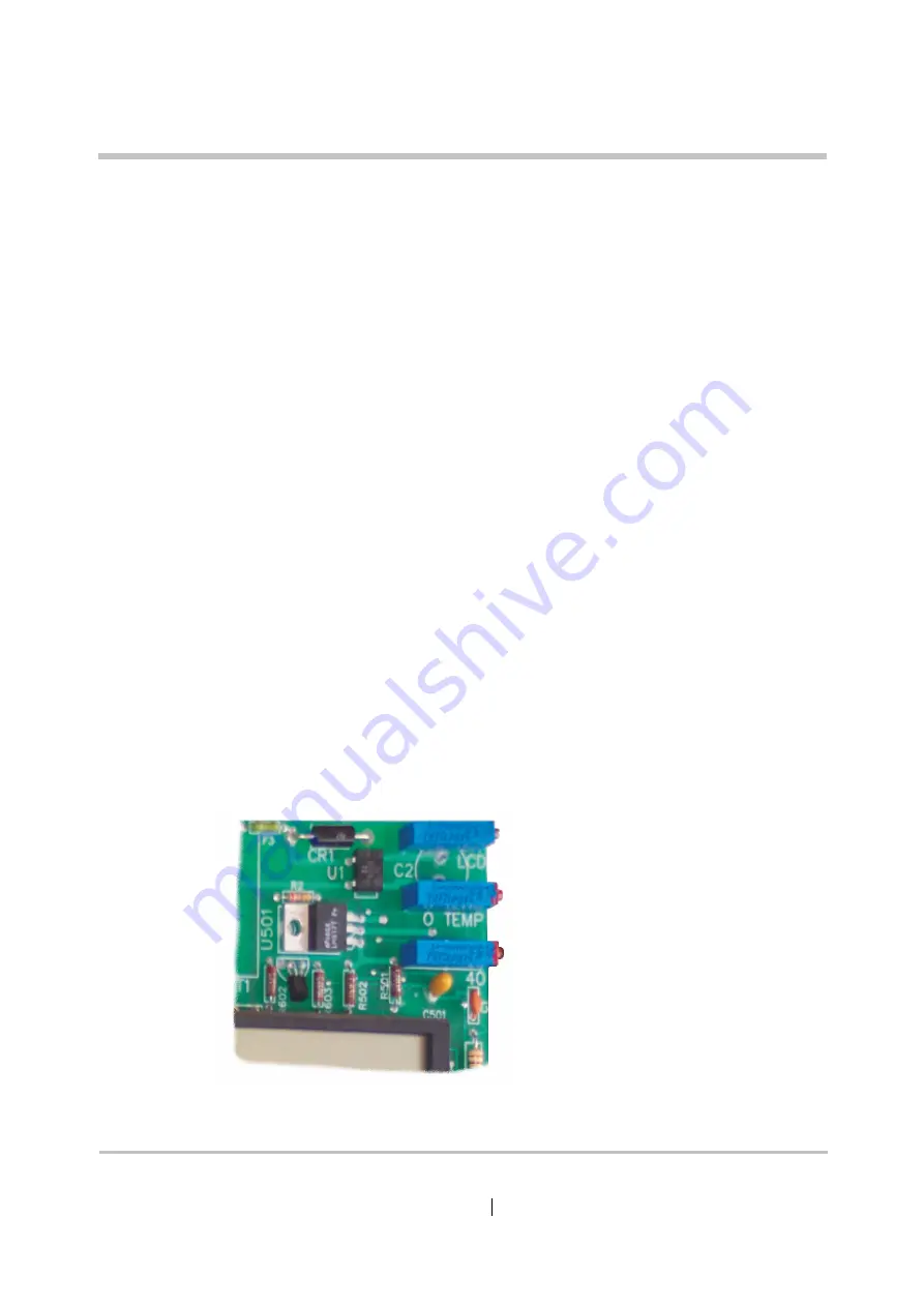
Set Recirculating Solution Temperature
Used to align the displayed
temperature with the actual
water temperature
LCD
O TEMP
H2O
Adjusts the set point for
the Over Temperature Alarm
Sets the operating point of
the temperature control circuit.
On older pumps this may be
labelled “40” as shown here.
LVL1-HL90_8504-GB-A
Figure 5 - 6: Purpose of the Pots
Summary of Contents for level 1 HOTLINE HL-90
Page 1: ......
Page 14: ...Introduction Specifications Blood and Fluid Warmer ...
Page 20: ...Sub Assemblies Blood and Fluid Warmer ...
Page 28: ...Technical Description Blood and Fluid Warmer ...
Page 45: ...Disassembly Procedures Blood and Fluid Warmer ...
Page 58: ...Blood and Fluid Warmer Maintenance Testing and Calibration ...
Page 83: ...Troubleshooting Blood and Fluid Warmer ...
Page 88: ...Spare Parts Blood and Fluid Warmer ...
Page 96: ...Rounding Off Blood and Fluid Warmer ...
Page 106: ...Appendix 1 Circuits Blood and Fluid Warmer ...
Page 110: ...Appendix 2 PCB Layout Blood and Fluid Warmer ...
Page 115: ...Appendix 3 Symbols Glossary Blood and Fluid Warmer ...
Page 118: ...Appendix 4 Frequently Asked Questions Information Bulletins Blood and Fluid Warmer ...
Page 132: ...Ndjg CdiZh 9 V gVbh ...


