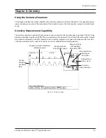
Chapter 8: Oximetry
Veterinary 3 Parameter Advisor
®
Operation Manual
8-5
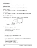
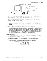
If necessary, connect the sensor to the patient cable.
4.
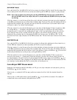
Connect the patient cable to the monitor. Align the pins
5.
on the patient cable with the monitor’s SpO
2
receptacle
and push the connector firmly into the receptacle.
The monitor will automatically detect when the SpO
•
2
patient cable is connected and the oximetry parameter
will be active.
Attach the sensor to the patient.
6.
Make sure the red light in the sensor is illuminated.
a.
Make sure the SPO
b.
2 SENSOR message is displayed
Select the appropriate sensor size; either for a
c.
small/medium animal, or for a large animal. See the
Application Guide
in this chapter for information
regarding sensor application.
ECG
NIBP
BP2
BP1
TEMP
SPO2
w
2
1
2
100-240AC
0.8A 50-60 Hz
F 1.6A/250V
REPLACE FUSE AS MARKED
RISK OF FIRE
WARNING:
CAUTION
Connect the
SpO
2
Patient
Cable
Application Guide
Universal “C” Sensor (V1707)
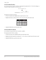
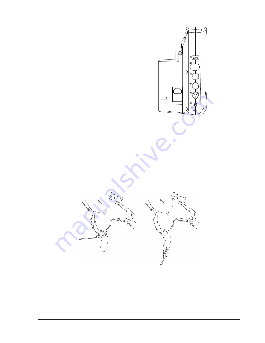
The ‘C’ Sensor is designed specifically for use in the larger tissue areas. It has brighter LED’s and therefore will
shine through thicker tissues. The ‘C’ Sensor can effectively be applied to the tongue or lip of larger dogs and
horses. It can also be applied across the Achilles tendon, across the metatarsals or metacarpals of cats and
dogs, on vulva, tails, and across the front leg of smaller animals. The tissue must be at least as thick as the space
between the two LED’s on the ‘C’ Sensor to get an SpO
2
reading.
Figure 8.4: Universal ‘C’ Sensor
Measured values for oximetry (%SpO
2
and PPR) will be displayed in the SpO
2
parameter box and an SpO
2
waveform, or plethysmogram, will appear on the display.
Figure 8.3: Connect the SpO
2
Cable


