DOWNMAST TRANS CEIVER (CTX-A9)
20
The fol
low
ing points must be con
sid
ered when
se lect ing a suit able site for the Downmast Trans ceiver:
(1) The transceiver is designed for bulkhead
mounting.
(2) Consideration must be given to accessibility for
servicing and protection from adverse conditions.
For ease of maintenance, the top of the
transceiver should not be mounted more than
1.6m above the deck.
(3) Ensure that there is sufficient space below the unit
for cable entries, and above the unit to allow for
connection of the semi-rigid co-axial cable
coupling.
NOTE:
The semi-rigid co-axial cable has a minimum bend radius
of 100 mm (4")
(4) The transceiver should be mounted in a position
which allows for ventilation and cooling.
(5) Do not fit the transceiver in an acoustic, noise
sensitive area, i.e. Bridge or Operations Room.
(6) Do not fit the transceiver in close proximity to any
magnetic compass or D/F aerial.
(7) Con necting ca bles be tween the dis play and the
trans ceiver should be lim ited to a length of 65
metres. Where the dis tance be tween trans ceiver
and dis play ex ceeds 65 metres, advice must be
obtained from Kelvin Hughes Ltd. Details of Line
Amplifiers and Receivers for use with long cable
runs are provided in Annex A to this manual.
21
Ca ble runs be tween the trans ceiver and the an tenna
turn
ing mech
a
nism should be kept to a min
i
mum
length, i.e. less than 35m, with as few bends and twists as
pos si ble. Sup porting brack ets and cou plings are to be used
to elim i nate the ef fects of vi bra tion.
22
Cable runs between the transceiver and the antenna
turning mechanism should be kept to a minimum
length, i.e. Less than 35m, with as few bends and twists as
possible. Supporting brackets and couplings are to be used
to eliminate the effects of vibration.
SOFT START UNIT (CZZ-A14)
23
The Soft Start Unit must be sited near the transceiver.
24
The Soft Start Unit must be sited to al low re moval of
the front cover.
OP TIONAL MAINS ISO LA TOR (80-261-600)
25
The Mains Iso
la
tor must be sited ad
ja
cent to the
dis play or in the area of the op er a tors con trol room and
con nected in par al lel with the main dis play.
IN STAL LA TION
SOFT START UNIT (CZZ-A14)
Fitting Ther mal Over load Trip Unit To Soft Start Unit
(CZZ-A14)
26
The ther
mal over
load trip unit is sup
plied with the
gear box fit ting kit.
27
Re move the soft start unit cover by re leas ing the four
cap tive screws.
28
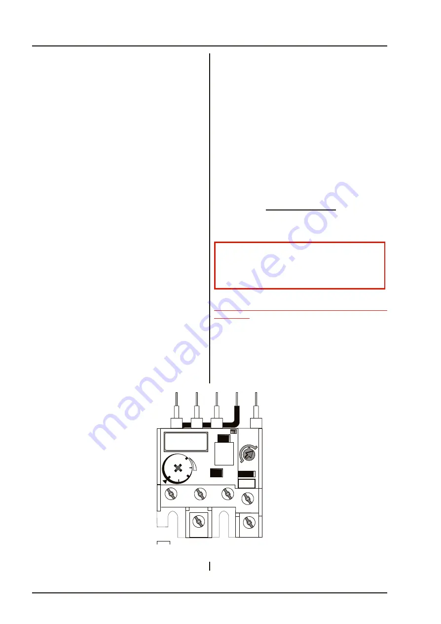
The trip unit, shown in Fig ure 1e, clips on the side of the
contactor and is se
cured in po
si
tion with re
lay
ter mi na tion screws 2T1, 4T2, 6T3, 14NO and A2.
May 01
4e.2
Original
KH 2020
Chap 4e
2'2
2'
7
A
I
O
H
2T1
4T7
14/22
95
NC
6T3
A2/96
NC
3'
2
CD-0224
Figure 1e - Thermal Overload Trip Unit
WARNING
EN SURE THAT ALL POWER SUP PLIES IN THE
VI CIN ITY OF THE SOFT START UNIT ARE
ISO LATED BE FORE ANY IN STAL LA TION TAKES
Summary of Contents for Kelvin Hughes Nucleus 3 5000 Series
Page 27: ...THIS PAGE IS INTENTIONALLY BLANK Sep 01 ii Amdt 1 KH 2020 Index Introduction ...
Page 73: ...THIS PAGE IS INTENTIONALLY BLANK KH 2020 Chap 2a July 03 2a 6 Amdt 5 ...
Page 101: ...THIS PAGE IS INTENTIONALLY BLANK May 01 3 6 Original KH 2020 Chap 3 ...
Page 109: ...THIS PAGE INTENTIONALLY BLANK July 03 viii Amdt 5 KH 2020 Index Chap 1 3 ...
Page 119: ...THIS PAGE IS INTENTIONALLY BLANK Sep 01 x Amdt 1 KH 2020 Contents Chap 4 5 ...
Page 150: ...THIS PAGE IS INTENTIONALLY BLANK May 01 4b 12 Original KH 2020 Chap 4b ...
Page 157: ...THIS PAGE IS INTENTIONALLY BLANK May 01 4c 6 Original KH 2020 Chap 4c ...
Page 163: ...THIS PAGE IS INTENTIONALLY BLANK May 01 4c 14 Original KH 2020 Chap 4c ...
Page 176: ...THIS PAGE IS INTENTIONALLY BLANK May 01 4c 28 Original KH 2020 Chap 4c ...
Page 234: ...THIS PAGE IS INTENTIONALLY BLANK May 01 4f 6 Original KH 2020 Chap 4f ...
Page 257: ...THIS PAGE IS INTENTIONALLY BLANK May 01 4f 30 Original KH 2020 Chap 4f ...
Page 275: ...THIS PAGE IS INTENTIONALLY BLANK July 03 5 18 Amdt 5 KH 2020 Chap 5 ...
Page 279: ...THIS PAGE IS INTENTIONALLY BLANK Sep 01 iv Amdt 1 KH 2020 Index Chap 4 5 ...
Page 309: ...THIS PAGE IS INTENTIONALLY BLANK Sep 01 xiv Amdt 1 KH 2020 Contents Chap 7 8 ...
Page 356: ...Original 7c 19 May 01 KH 2020 Chap 7c CD 2413 Figure 16c Modulator PCB Switches Test Points ...
Page 359: ...THIS PAGE IS INTENTIONALLY BLANK May 01 7c 22 Original KH 2020 Chap 7c ...
Page 381: ...THIS PAGE IS INTENTIONALLY BLANK Sep 01 7d 26 Amdt 1 KH 2020 Chap 7d ...
Page 425: ...THIS PAGE IS INTENTIONALLY BLANK May 01 8a 22 Original KH 2020 Chap 8a ...
Page 445: ...THIS PAGE INTENTIONALLY BLANK July 03 8aA 16 Amdt 5 KH 2020 Chap 8a Annex A ...
Page 463: ...THIS PAGE IS INTENTIONALLY BLANK May 01 8c 12 Original KH 2020 Chap 8c ...
Page 472: ...THIS PAGE IS INTENTIONALLY BLANK May 01 8c 22 Original KH 2020 Chap 8c ...
Page 476: ...THIS PAGE IS INTENTIONALLY BLANK May 01 8d 4 Original KH 2020 Chap 8d ...
Page 498: ...THIS PAGE IS INTENTIONALLY BLANK Original 8e 19 May 01 KH 2020 Chap 8e ...


