background image


6


Taifun


GT one 

®


REGULATION OF AIR SUPPLY 

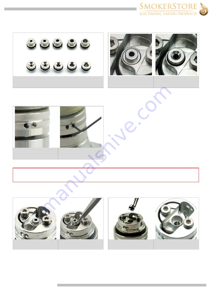
The true control of the air supply takes place inside the device. In the base there is an Air Pin with an inner diameter of 1.2 mm. Optionally, other Air Pin variants 
with diameters of 0.8 mm, 1.0 mm, 1.5 mm and 1.8 mm are available. When inserting the Air Pin, make sure to insert it with the bottom side facing down. 


From left to right:  

0.8 mm / 1.0 mm / 1.2 mm (standard) / 1.5 mm / 1.8 mm 


Air Pin used correctly 

Air Pin used incorrectly 

For the external air supply, there are two air holes in the base, one of them can optionally be closed with a grub screw. This grub screw can be inserted with the 0.9 
mm Allen key if necessary. Depending on your own draw technique and the amount of nicotine in the liquid, the insertion of the grub screw can increase the 
noticeable throat hit. However, it should be noted that the air supply is primarily limited by the inserted air pin inside the vaporizer. The left hole has an air inlet with 
a diameter of 2.2 mm. The right hole has an air inlet with a diameter of 1.6 mm. 


IMPORTANT 

The outer set screw is not used to regulate the air volume in the sense of an airflow control. For a smooth vapor experience you leave 
both channels open and regulate the draw resistance via the inner Air Pin.  


INSERT / REMOVE AIR PIN  

We recommend using tweezers to insert or remove/replace the air pin. Make sure that the Air Pin is always inserted with the bottom side facing down. 


Top side 

Bottom side 

Summary of Contents for Taifun GT one

Page 1: ...e an asthma attack shortness of breath and coughing fits in the case of a previously damaged lung If complaints occur please seek medical attention immediately Do not use our product if you have a kno...

Page 2: ...ble of performance use of mods without protection is not recommended 3 MANUFACTURER RECOMMENDATIONS Adjust the power of your mod to an appropriate level depending on the used coil 4 STORAGE INSTRUCTIO...

Page 3: ...ll 1x Tank Section Tankshield 1x Tank Section PSU Tank 1x O Ring NBR 50 17x1 5 mm 1x O Ring NBR 50 15x1 mm 1x Positive Pole 1x Screw M2x4 mm 1 x O Ring NBR 70 8x1 mm 1x Air Pin 1x O Ring NBR 70 2x1 mm...

Page 4: ...e screws Then bend the wire ends and retighten the screws D and O again This fixes the coil in place With a winding aid the coil can still be aligned somewhat Cut off the exceeding ends of the wire Th...

Page 5: ...ank at a slight angle at the beginning Carefully fill the liquid into the tank along the edge During filling slightly raise the tank again so that you can see the filling level Stop filling as soon as...

Page 6: ...the 0 9 mm Allen key if necessary Depending on your own draw technique and the amount of nicotine in the liquid the insertion of the grub screw can increase the noticeable throat hit However it should...

Page 7: ...g the device from the mod or by switching off the mod ASSEMBLING DEVICE The device is usually delivered fully assembled the following instructions are for the assembly after cleaning Moistening the se...

Page 8: ...horized dealers Before replacing the PSU Tank the atomizer must be completely emptied REPLACING SEALING RINGS Sealing rings are used to seal the device If you notice liquid or moisture leaking out of...

Reviews: