HEX390 Installation & Commissioning Instructions September 2016
11
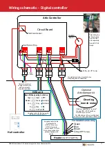
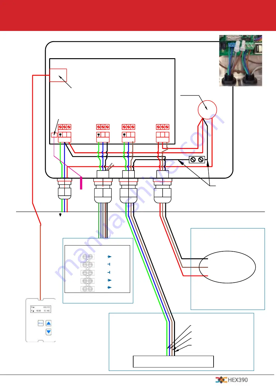
Wiring schematic - Digital controller
P
N
P1
N
P3
N
NC
C
240VAC
MOTOR
HEAT
Vent
Circuit Board
Patch lead socket
Isolator
Switch.
NO
Heat Sensor Plug.
Grey (HT15D Only)
Green
Blue
Brown
Grey
Mode
Dry-Matic
Fan
Diverting
Branch
Motor
Heater
1
2
3
N P
P
N
If damper operates in "reverse"
change CW<>CCW switch on
motor body to correct.
For digital controller, mount attic box
with pack glands downwards
Supplied cable for the
duct heater for
HT07 is three core.
HT15 is four core
- wire to earth, P3 & N.
Note wiring connection
details supplied with
heater.
Attic Controller
(for HT15 only)
Heater
(for HT07 &HT15)
Optional
Attic damper kit
1
2
3
P
N
P1
N
P3
N
NC
C
240VAC
MOTOR
HEAT
Vent
Circuit Board
Patch lead socket
Isolator
Switch.
NO
Heat Sensor Plug.
Grey (HT15D Only)
Green
Blue
Brown
Grey
Mode
Dry-Matic
Fan
Diverting
Branch
Motor
Heater
1
2
3
N P
P
N
If damper operates in "reverse"
change CW<>CCW switch on
motor body to correct.
Diverting
branch motor
Hall controller
For heated units only
Heat
sensor
For attic damper kit, ensure the heat
sensor is in duct, upstream of filter box.
High
Medium
Terminate
Terminate
E
Black
Brown
Grey
Blue
Grn/Yel
Basic HEXbody wiring to attic box
Supplied cable for the fan unit is
five core - wire to N & P1
(HT15 only)
N
E
P1
Low
N
HEX unit
Terminate
seperately
Cable for electrical
supply is three core
and pre-wired to
the attic controller.
NO NC
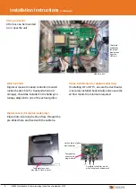
See p8 for full
image
Terminate grey
& brown wires
from the HEX
unit separately


