background image

Assembly Instructions  

Assembly


The Smooth 5.3P


treadmill is shipped in one piece to make assembly easy.  After opening the 

box, remove any packing materials from the treadmill.  Do not throw away any packing materials 
until the unit is working properly.  Place the base on a clean, level surface.  Make sure the 
electrical cord will easily reach an electrical outlet. 

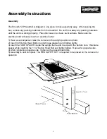
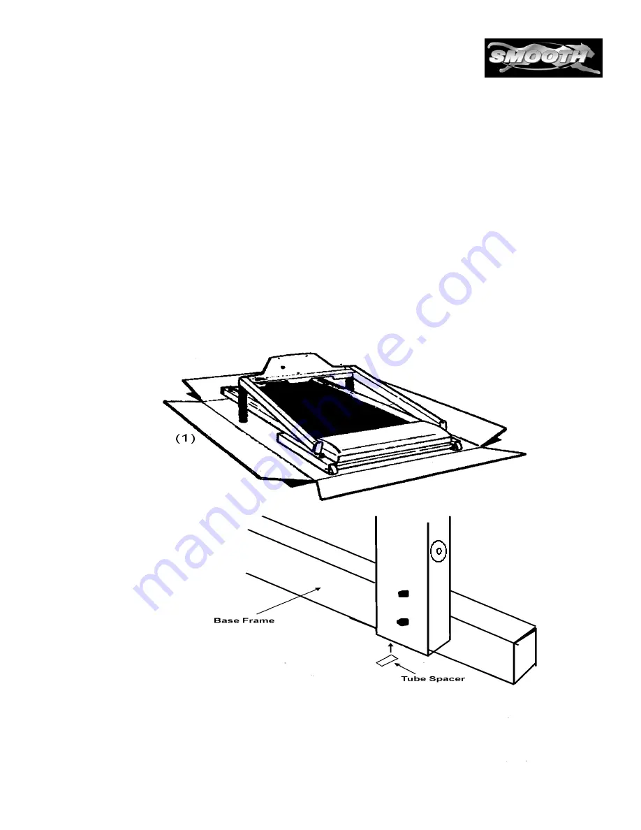
1) Have a second person raise the console to the upright position and hold. 
2) Insert 3/4” Button Head Bolts in upright (see diagram) and tighten lightly.  
3) Insert the TUBE SPACER inside the upright frame and line up with the bottom hole.  Hold tube 
spacer while inserting the 1 1/2” Button Head Bolt and lightly tighten.  Repeat for opposite side. 
4) After completing opposite side, Tighten all four assembled bolts.   
5) Assembly is now complete. The RED SAFETY KEY is required to be placed on the console for 
operation. 
 

Insert 3/4” bolt 

Summary of Contents for 5.3P

Page 1: ...dmillbynet com advancedfitness com The Fitness Superstore SALES 888 9TREADS 888 987 3237 SERVICE 888 340 0482 SMOOTH is a registered trademark of Internetfitness com Mt Laurel NJ O W Smooth 5 3P Tread...

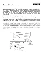
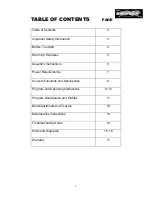
Page 2: ...m Up Exercises 5 Assembly Instructions 6 Power Requirements 7 Console Functions and Descriptions 8 Program and Operating Instructions 9 10 Program Descriptions and Profiles 11 Belt Adjustments and Ten...

Page 3: ...in regards to plugging in your treadmill Keep the power cord away from the incline wheels and do not run the power cord underneath your treadmill Do not operate the treadmill with a damaged or frayed...

Page 4: ...increments as this treadmill is capable of high speeds If you are taking medication consult your physician to see if the medication will affect your exercise heart rate If you have heart problems you...

Page 5: ...tretching and light exercise to warm up The drawings on this page show several forms of basic stretching you may perform before your workouts Again consult a physician before starting this or any othe...

Page 6: ...an electrical outlet 1 Have a second person raise the console to the upright position and hold 2 Insert 3 4 Button Head Bolts in upright see diagram and tighten lightly 3 Insert the TUBE SPACER inside...

Page 7: ...r treadmill Surge protectors can be purchased at most hardware stores The manufacturer recommends a single outlet surge protector with a UL 1449 rating as a Transient Voltage Surge Suppressor TVSS wit...

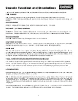
Page 8: ...peed selected In program mode the change in speed with the Speed Bar will only work in the current interval Once the program switches to another interval the speed will revert to the programmed speed...

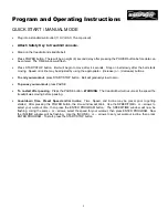
Page 9: ...s START STOP button Belt will gradually slow to zero To pause your workout press PAUSE To re start after pausing Press the PAUSE button WARNING The treadmill belt will resume at the speed the treadmil...

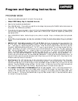
Page 10: ...to select your workout time then press the ENTER PROGRAM button The SPEED TIME window will now be flashing Using the same or arrows select the speed for your workout then press ENTER PROGRAM Now the I...

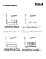
Page 11: ...nd gradually decrease speed and elevation in the last segment cool down The Speed Intervals Program is designed to vary treadmill speed while maintaining a constant elevation The Rolling Hills Program...

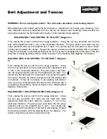
Page 12: ...Walking Belt Slipping instructions WALKING BELT HAS SHIFTING TO THE RIGHT Diagram 2 First unplug the power cord from the surge protector Using the hex key provided turn the right rear roller adjustmen...

Page 13: ...be lubricated usually within the first year or 500 hours of use If you have questions call us at 888 340 0482 Every 30 days or 30 hours of operation lift the sides of the walking belt and feel the to...

Page 14: ...n 2 Check the house electrical breaker box and the circuit breaker for the room the treadmill is located in If it has tripped reset or have an electrician replace the breaker in home If treadmill stil...

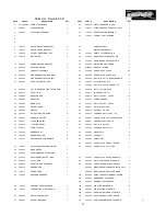
Page 15: ...3 8 16 NYLOCK 2 27 06 0008 END CAP 1 81 02 0018 PUSH NUT 3 8 HAT 4 28 06 0009 S E S EXTENSION GLIDE 4 82 02 0019 CARRIAGE BOLT 10 24 X 1 1 2 4 29 06 0019 BASE PAN CENTER 1 83 02 0020 SCREW 1 4 20 X 2...

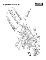
Page 16: ...16 Exploded View 5 3P...
Page 17: ...dent misuse or abuse b by the use of parts not manufactured or sold by Smooth c by modification of the Product or normal wear and tear d operation on incorrect power supplies or e as a result of servi...

Reviews: