www.smoothfitness.com
23
ASSEMBLY
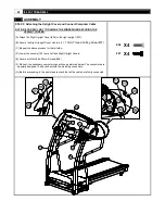
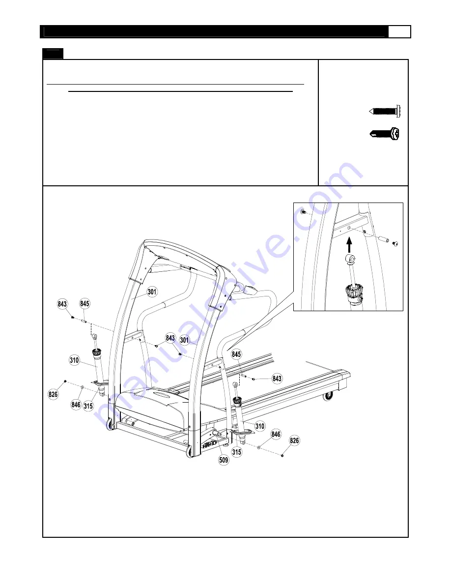
STEP 6
:
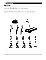
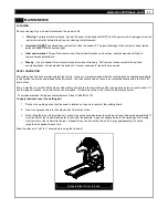
Attach the Outside Upright Covers
NOTE: CAREFULLY FOLD THE COMPUTER CABLES AND TUCK THEM BETWEEN THE
PLASTIC RIDGES OF PARTS 304 AND 305 SO THEY WILL NO BE PINCHED.
(A) Secure the ground wire onto the Right upright with one
4 × 15mm Thread Cutting Screw
(807).
(B) Attached the Upright Cover (306) to the right side Upright Tube.
(C) Secure using two #8 x 20mm Screws (806) into the console.
(D) Then secure using two
4 × 15mm Thread Cutting Screw
(807) into the Upright Tube.
(E) Repeat this process for the left side.
806
x4
807
X5
Summary of Contents for 9.45ST
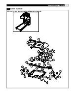
Page 11: ...www smoothfitness com 11 PARTS DIAGRAM MOST OF THE PARTS SHOWN HERE HAVE BEEN PRE ASSEMBLED ...
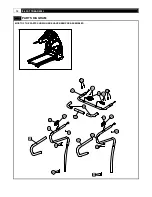
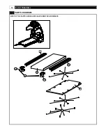
Page 12: ...12 9 45ST TREADMILL PARTS DIAGRAM MOST OF THE PARTS SHOWN HERE HAVE BEEN PRE ASSEMBLED ...
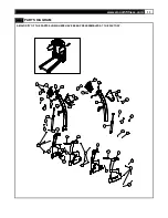
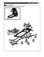
Page 14: ...14 9 45ST TREADMILL PARTS DIAGRAM MOST OF THE PARTS SHOWN HERE HAVE BEEN PRE ASSEMBLED ...

