background image

28 

SMOOTH CE3.6 ELLIPTICAL 


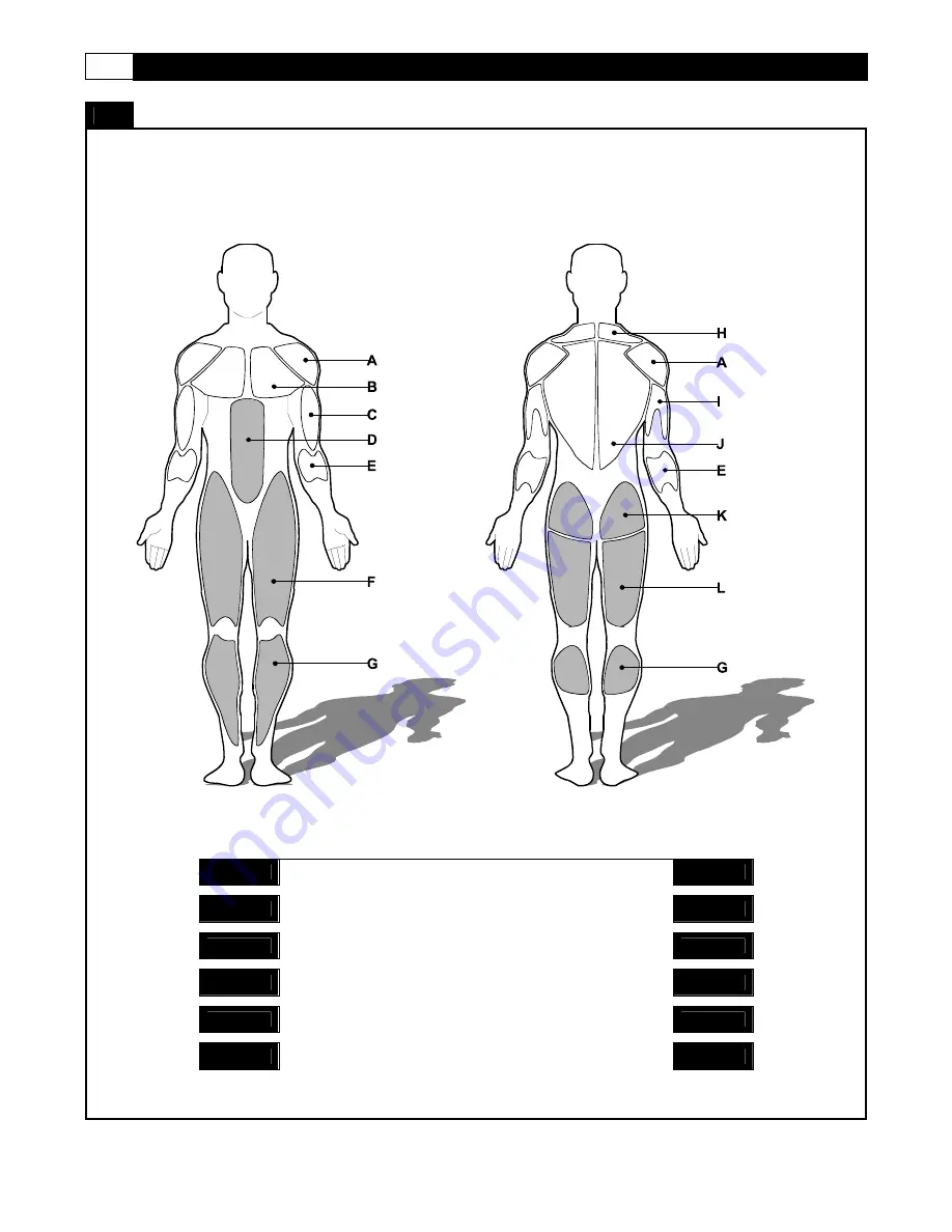
MUSCLE CHART 

Targeted muscle groups

 
The exercise routine that is performed on this product will develop primarily lower body muscle groups.  These muscle groups are 
shown in gray color on the chart below. 


MUSCLE GROUPS 

Shoulder muscles 

Calf muscles 

Pectoral muscles 

Trapezius muscles 

Bicep muscle 

Tricep muscles 

Abdominal muscles 

Back muscles 

Forearm muscles 

Gluteal muscles 

Quadricep muscles 

Hamstring muscles 


Summary of Contents for CE-3.6 ELLIPTICAL

Page 1: ...USER S MANUAL SMOOTH CE3 6 ELLIPTICAL USER WEIGHT LIMITATION 325lbs 145kgs SERIAL NUMBER found on frame...

Page 2: ...all the necessary tools you may require to assemble the unit properly Having all of the necessary equipment at hand will save time and make the assembly quick and hassle free Clear your work area Mak...

Page 3: ...ver 1 305 Upright Upper Cover 1 2 306 Upright Upper Cover 2 2 307 Upright Lower Cover Right 2 308 Upright Lower Cover Left 2 315 Action Handlebar Cover 2 316 Action Handlebar Inside Cover 4 320 Pedal...

Page 4: ...e sizes listed No Description Qty 701 M14x91mm Bolt 2 708 M8x60mm Bolt 2 709 M10x94mm Bolt 2 710 M8x65mm Bolt 2 719 M14 Nut 2 722 8x21x2mm Cup Washer 2 726 4x19mm Screw 19 728 4x12mm Screw 8 729 M10 N...

Page 5: ...Grip 2 CE3 6 202 203 Handlebar End Cap 2 CE3 6 203 204 7pin Computer Wire Middle 1 CE3 6 204 205 Hand Pulse Sensor Wire Middle 2 CE3 6 205 300 301 Action Handlebar Left 1 CE3 6 301 302 Action Handleb...

Page 6: ...E3 6 502 503 Crank 2 CE3 6 503 504 Belt 1 CE3 6 504 506 Rear Stabilizer Cap 2 CE3 6 506 507 Rear Stabilizer Cushion 2 CE3 6 507 509 Strengthen Wheel Adjuster Set 1 CE3 6 509 510 Flywheel Pivot 1 CE3 6...

Page 7: ...706 707 M8x90mm Bolt 4 CE3 6 707 708 M8x60mm Bolt 2 CE3 6 708 709 M10x94mm Bolt 2 CE3 6 709 710 M8x65mm Bolt 2 CE3 6 710 711 M8x30mm Bolt 2 CE3 6 711 712 M10x45mm Bolt 2 CE3 6 712 713 M10x45mm Bolt 2...

Page 8: ...748 751 M5x14mm Bolt 4 CE3 6 751 752 M5x10mm Bolt 2 CE3 6 752 753 M6x15mm Bolt 2 CE3 6 753 754 6 5x12x1mm Washer 6 CE3 6 754 755 8x16 5x1 5mm Washer 11 CE3 6 755 760 M8x15mm Bolt 4 CE3 6 760 761 M5 Nu...

Page 9: ...itness com 9 PARTS DIAGRAM 201 203 109 105 111 753 112 111 113 116 752 752 117 115 114 753 106 107 106 118 109 732 751 732 104 103 102 101 110 203 202 205 204 205 202 726 119 205 205 709 709 731 731 7...

Page 10: ...ASSEMBLED 708 320 318 708 728 710 303 320 732 314 315 304 315 317 732 313 728 728 710 317 313 316 308 314 313 316 307 302 311 726 306 312 305 310 726 309 319 319 306 305 308 307 726 726 726 726 726 3...

Page 11: ...EEN PRE ASSEMBLED 407 705 707 705 413 401 414 415 715 413 417 402 715 414 415 407 412 701 320 417 705 716 726 726 716 417 726 417 403 403 320 701 412 404 404 707 405 718 404 404 405 705 406 706 715 40...

Page 12: ...15 503 518 504 503 527 711 532 519 507 726 515 729 704 507 704 726 712 506 712 506 514 517 516 703 760 715 526 523 713 517 514 521 509 724 725 501 721 520 521 525 702 716 730 524 531 723 528 527 530 5...

Page 13: ...thfitness com 13 PARTS DIAGRAM MOST OF THE PARTS SHOWN HERE HAVE BEEN PRE ASSEMBLED 603 607 726 726 604 726 601 727 606 727 606 727 606 606 606 761 870 762 754 762 761 870 602 726 727 726 605 606 727...

Page 14: ...14 SMOOTH CE3 6 ELLIPTICAL WIRE DIAGRAM MOST OF THE PARTS SHOWN HERE HAVE BEEN PRE ASSEMBLED 205 205 205 205 204 106 107 106 321 321 321 321 204 522 522 522 540 540 607 607 607...

Page 15: ...in Computer Wire Middle 204 to the 7pin Computer Wire Lower 522 B Attach the Console Support Upright 201 to the Main Frame 501 and secure using the M10x94mm Bolt 709 10 5x28x2mm Cup Washer 731 and M10...

Page 16: ...L ASSEMBLY STEP 2 A Slide the Acton Handlebar Left 301 and Action Handlebar Right 302 to the Console Support Upright 201 B Connect the Hand Pulse Sensor Wire Middle 205 to Hand Pulse Sensor Wire Lower...

Page 17: ...3 A Attach the Left Upright and Right Upright to the Console Support Upright 201 and secure using M8x65mm Bolt 710 on top of upright M8x60mm Bolt 708 and 8x21x2mm Cup Washer 722 on bottom of upright 7...

Page 18: ...EMBLY STEP 4 A Slide the M14x91mm Bolt 701 through the Pedal Arm Right 401 and Action Handlebar Right 302 and secure the M14 Nut 719 as shown Repeat the above procedure to assemble the Left side 701 X...

Page 19: ...TEP 5 A Attach the Pedal Arm Front Pivot Cover 320 into the ends of the Action Handlebar Right 302 and Pedal Arm Right 401 Repeat the procedure on the Pedal Arm Left 402 and Action Handlebar Left 301...

Page 20: ...ch the Front Frame Cover Upper 524 and Front Frame Cover Lower 523 to the Main Frame 501 Secure with Fixing Inserts 716 and 4x50mm Bolt 730 NOTE The Fixing Insert 716 has been pre assembled to Front F...

Page 21: ...ecure with four 4x15mm Screws 732 Then attach two Action Handlebar Inside Covers 316 from the back side of the Action Handlebar Right 302 to the Action Handlebar Cover 315 Secure the Action Handlebar...

Page 22: ...ght Lower Cover Left 308 and Upright Lower Cover Right 307 to Right Upright 304 using four 4x19mm Screw 726 Repeat this procedure on Left Upright 303 with Upright Lower Cover Left 308 and Upright Lowe...

Page 23: ...he Upright Upper Cover 1 305 and Upright Upper Cover 2 306 to Upright using one Fixing Insert 716 and four 4x19mm Screws 726 NOTE The Fixing Insert 716 has been pre assembled onto Upright Upper Cover...

Page 24: ...Hand Pulse Sensor Wire Middle 205 as shown below A Attach the Computer to the Console Support Upright 201 using two M5x14mm Bolts 751 B Attach the Console Back Cover 119 to the Console and secure usi...

Page 25: ...itness com 25 iPod MOUNTING INSTRUCTION iPod MOUNTING INSTRUCTION 1 Attach your iPod into the dock 2 Rotate the iPod to lay on the bracket 3 Adjust the intensity of volume on computer buttons while pl...

Page 26: ...as you will need to tip the CE3 6 elliptical Trainer while adjusting the levelers Tip the AGILE Dynamic Motion Trainer to the left right You will then see the LEVEL ADJUSTERS These will need to be scr...

Page 27: ...www smoothfitness com 27 TRANSPORT INSTRUCTION TRANSPORT INSTRUCTIONS To transport your CE3 6 elliptical Trainer simply lift the back end and roll it away to the desired location as shown...

Page 28: ...p primarily lower body muscle groups These muscle groups are shown in gray color on the chart below MUSCLE GROUPS A Shoulder muscles Calf muscles G B Pectoral muscles Trapezius muscles H C Bicep muscl...

Page 29: ...er Thigh Stretch Sit with the soles of your feet together with your knees pointing outward Pull your feet as close into your groin as possible Gently push your knees towards the floor Hold for 15 coun...

Page 30: ...RPM B GENDER C AGE D WEIGHT E HEIGHT F TIME G RESISTANCE LEVEL H PULSE I DISTANCE PROGRAM J MODE BUTTON K STOP BUTTON L iPod VOL CONTROLS M RESISTANCE DOWN N ENTER BUTTON O FAN CONTROL P START BUTTON...

Page 31: ...on status when the computer is in the SLEEP MODE PAUSE MODE While in the PROGRAM without pedalling the machine for 30 seconds the console will enter the PAUSE MODE During the PAUSE MODE if you start p...

Page 32: ...EIGHT and begin flashing Press the UP DOWN button to adjust the user height information and then press ENTER to confirm USER WEIGHT After the HEIGHT has been confirmed the TIME display will show WEIGH...

Page 33: ...will show the DISTANCE setting of 3 2mph or 5 0km h press the up and down button to adjust target DISTANCE then press ENTER to confirm Press the START button to begin the exercise program To increase...

Page 34: ...you were using a program that has higher levels of resistance over a shorter period of time The RESISTANCE display will show 1 To increase or decrease the resistance while exercising press the UP DOW...

Page 35: ...e the program To increase or decrease the resistance while exercising press the UP and DOWN button Computer will automatically adjustment resistance to conform user set Watt during difference rpm exer...

Page 36: ...ng and continue at the same resistance until the 3 minute warm up is completed and then go into the Target pulse main program If you cannot reach the target warm up pulse in 3 minutes the program will...

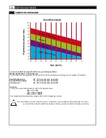
Page 37: ...nt you may not have full contact with the sensors or not enough of your palm on the sensor Remove your hand and place it over the sensor again Heart Rate Training To maximize your results from trainin...

Page 38: ...ld train with the following percentage of your maximum heartrate Health Fat Burning 65 75 of your max heartrate Fitness Bodyshaping 75 85 of your max heartrate Performance 85 95 of your max heartrate...

Page 39: ...ce on a Smooth Fitness product call Smooth Fitness In the instance that service is not available in an area Smooth Fitness at its discretion can either 1 find a service technician in your area to perf...

Page 40: ...40 SMOOTH AGILE TRAINER Smooth Fitness 780 5th Ave King of Prussia PA 19406 Toll Free Customer Service 1 888 800 1167 Website www smoothfitness com...

Reviews: