background image


12 


Moving the Sit N Cycle and Resistance Adjustment

” 


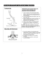
1.  Lower the seat to the lowest height setting. 

Prior to moving the unit verify that the seat is 
locked in place and the seat adjustment knob 
is fully tightened. 

2.  There is a transportation handle the under the 

back of the seat. 

3.  Hold the transportation handle and tilt the unit 

forward until the wheels are resting on the 
floor.(about 15 to 20 degrees). 

4.  Roll the unit forward to the desired location. 
5.  Once the unit is in place, verify that all 4 

stabilizing feet are firmly in contact with the 
floor. 

Failure to follow the instructions above may 
cause the seat to become disengaged from the 
unit frame during transportation


1.  There are numbers on the resistance dial 

ranging from 1 through 8. Number 1 is the least 
amount of resistance offered and number 8 is 
the maximum amount offered. 

2.  To increase the resistance, turn the dial 

clockwise. 

3.  To decrease the resistance, turn the dial 

counter-clockwise.


Verify that the seat is locked in place and 
cannot be removed. Verify the seat 
adjustment knob is fully tightened


Transporting 

Adjusting the Resistance 

Summary of Contents for sit N cycle SNC-II

Page 1: ...in producing this quality product and hope it will provide many hours of quality exercise to make you feel better look better and enjoy life to its fullest The Sit N Cycle is not a typical exercise b...

Page 2: ...2 Seat Cushion Disclosure ALL NEW MATERIALS Consisting of 100 Polyurethane Date of Manufacture 02 15 14 Model SNC II Lot 140213...

Page 3: ...balance while getting on this product using this product and getting off this product loss of balance may result in a fall and or serious bodily injury 12 The equipment should not be used by persons...

Page 4: ...shape and achieve a happier and healthier lifestyle Before reading further please review the drawing below and familiarize yourself with the parts that are labeled Read this manual carefully before us...

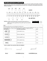
Page 5: ...ads are measured from below the head to the end of the bolt or screw Flat head bolts and screws are measured from the top of the head to the end of the bolt or screw Note Please review the contents of...

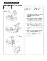
Page 6: ...d place it on to the Styrofoam as pictured on the left in Fig 1 A 3 Attach the base frame 13 to the main frame 8 To insure proper assemble make sure the frame is facing the correct direction The bolt...

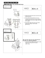
Page 7: ...over overlaps the main frame cover so that the seam between the covers is tight and there are no gaps 3 Secure the base frame top cover to the base frame using 4 34 screws M4 12mm 34 x 4 33 x 6 After...

Page 8: ...ght on the foot pads as pictured on the left STEP4 Pedal Covers 1 Locate the two pedal crank cover sets Note the covers are interchangeable from left to right sides 2 Slide one crank arm cover over th...

Page 9: ...ht side are determined from the seated position Failure to follow the above instructions may cause damage 2 Using your hands thread the Right Pedal CLOCKWISE onto the RIGHT crank arm After the pedal i...

Page 10: ...lts M8 13mm 3 x 5 STEP7 Seat Installation 1 To insert the seat turn the adjustment knob counter clockwise to loosen 2 Pull the knob outward and insert the seat at the same time until the seat post is...

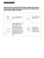
Page 11: ...knob to release the seat 3 While holding the knob out move the seat up or down The seat will move in a 45 degree motion Once the required height is reached release the knob and slowly push the seat d...

Page 12: ...5 Once the unit is in place verify that all 4 stabilizing feet are firmly in contact with the floor Failure to follow the instructions above may cause the seat to become disengaged from the unit frame...

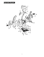
Page 13: ...13 Exploded Diagram...

Page 14: ...r 1 SNC 13 Base Frame 1 SNC 14 Base Frame Cover Lower 1 SNC 15 Foot Pad screw4 M8 9 4 SNC 16 M10xp1 25x13mm Allen Head Bolts 4 SNC 17 Wheel Pin 2 SNC 18 Wheel 2 SNC 19 Belt 1 1 SNC 20 Belt 2 1 SNC 21...

Page 15: ...nder This Warranty To help the technician assist you over the phone please have the following information ready Model name or number from the cover of the manual Serial number located on the frame of...

Page 16: ...16 Customer Service Toll Free 855 663 5643...

Reviews: