background image


11 

A

SSEMBLY

 I

NSTRUCTIONS

” 


S

TEP6

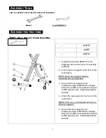
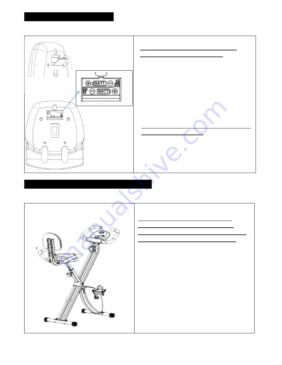
Battery Installation 


1.  Open the battery door on the back of the 

computer 

2.  Insert the batteries in the direction shown on 

the left. 

3.  Replace the battery door


Note: Batteries should be recycled or disposed of as 

per state and local guidelines.


S

EAT

 I

NSTALLATION


and

 A

DJUSTMENT

” 


Seat Installation


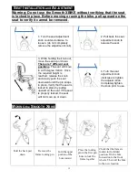
4.  To insert the seat, turn the adjustment knob 

counter clockwise to loosen. 

5.  Pull the knob outward and insert the seat at 

the same time, until the seat post is fully 
inserted and the seat rests on the main 
frame. 

6.  Release the knob and slowly pull up on the 

seat until it locks in place.   

7.  After releasing the pin and the seat is locked 

in place, verify that the seat will not move up 
or down. 

8.  Tighten the knob by turning it clockwise until 

it is completely tight

Note: Do not completely remove the 
adjustment knob from the frame. To 
adjust the seat you will need to loosen the 
knob and then pull the knob outward. 


Pull 


Note: The computer monitor will not 
function without 2 AA batteries. 


Summary of Contents for SMB-XBIKE

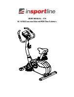
Page 1: ...OWNER S MANUAL CAUTION THE MAXIMUM USER WEIGHT LIMIT ON THIS PRODUCT SHOULD NOT EXCEED 136KG 300LBS The Product May Vary Slightly From the Picture Shown Above MADE IN CHINA VER 021114...

Page 2: ...2 Seat Cushion Disclosure ALL NEW MATERIALS Consisting of PP PU FOAM Date of Manufacture 2014 02 Model SMB XBIKE Lot DD6321 1...

Page 3: ...balance while getting on this product using this product and getting off this product loss of balance may result in a fall and or serious bodily injury 12 The equipment should not be used by persons w...

Page 4: ...rize yourself with the parts that are labeled Read this manual carefully before using the equipment ASSEMBLY PARTS Unpack the box in a clear area Follow the List of Assembly Parts below to check and m...

Page 5: ...bolt or screw Flat head bolts and screws are measured from the top of the head to the end of the bolt or screw Note The assembly hardware has been pre assembled Please review the contents of the hardw...

Page 6: ...he transport wheels attached 3 Secure the front support to the mainframe using 2 M8 50mm carriage bolts 10 2x M8 curved washers 9 and 2x M8 cap nuts 12 Completely tighten all bolts 4 Attach the rear s...

Page 7: ...16 3 Tighten all fasteners now After the seat has been attached and the fasteners are completely tightened 1 Secure the back pad frame to the seat post using 2x M8 50mm carriage bolts 10 2x M8 flat w...

Page 8: ...cks in place 4 Confirm that the seat is locked in place by lifting upward on the seat verifying that is does not move upward 5 Turn the knob clockwise until the knob is completely tight Seat Adjuster...

Page 9: ...time 4 Secure the left and right sides of the console frame to the main frame using 2x M6 12mm bolts 4 and 2x M6 flat washers 6 5 Fully tighten all fasteners now 4x 4 2x 5 2x 6 STEP5 Pedal Assembly NO...

Page 10: ...the RIGHT crank arm After the pedal is hand tightened use the supplied wrench to completely tighten the pedal 1 Using your hands thread the Left Pedal COUNTER CLOCKWISE onto the LEFT crank arm After t...

Page 11: ...ll the knob outward and insert the seat at the same time until the seat post is fully inserted and the seat rests on the main frame 6 Release the knob and slowly pull up on the seat until it locks in...

Page 12: ...motion Once the required height is reached release the knob and slowly push the seat downward until the pin snaps in place Verify that the seat is locked in place by pulling upward on the seat If the...

Page 13: ...e turn the dial counter clockwise Place the locking pin in the first pin hole to lock the frame in place Before using the bike test to make sure that the bike does not fold Remove the frame locking pi...

Page 14: ...F Pulse Displays your pulse when using the pulse handgrips To use the pulse grips place the palm of you hands on the silver pulse grips located on the computer handlebars After placing your hands on...

Page 15: ...seconds before displaying the next data reading Auto On To turn the bike on simply press the selection button or begin to pedal the bike Auto Shut Off The computer will automatically shut off when the...

Page 16: ...16 EXPLODED DIAGRAM...
Page 17: ...strap 1 XB 13 Pedal left 1 2 20 with strap 1 XB 9 Curved washer M8 6 XB 10 Carriage bolt M8 50 6 XB 11F Front support 1 XB 11R Rear support 1 XB 12 Cap nut M8 4 XB 14 Seat adjuster knob M12 1 75 1 XB...

Page 18: ...Under This Warranty To help the technician assist you over the phone please have the following information ready Model name or number from the cover of the manual Serial number located on the frame of...

Page 19: ...19 Customer Service Toll Free 855 663 5643...

Reviews: