

10
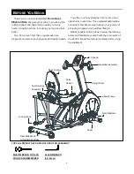
“
A
SSEMBLY
I
NSTRUCTIONS
”
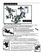
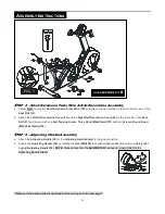
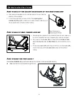
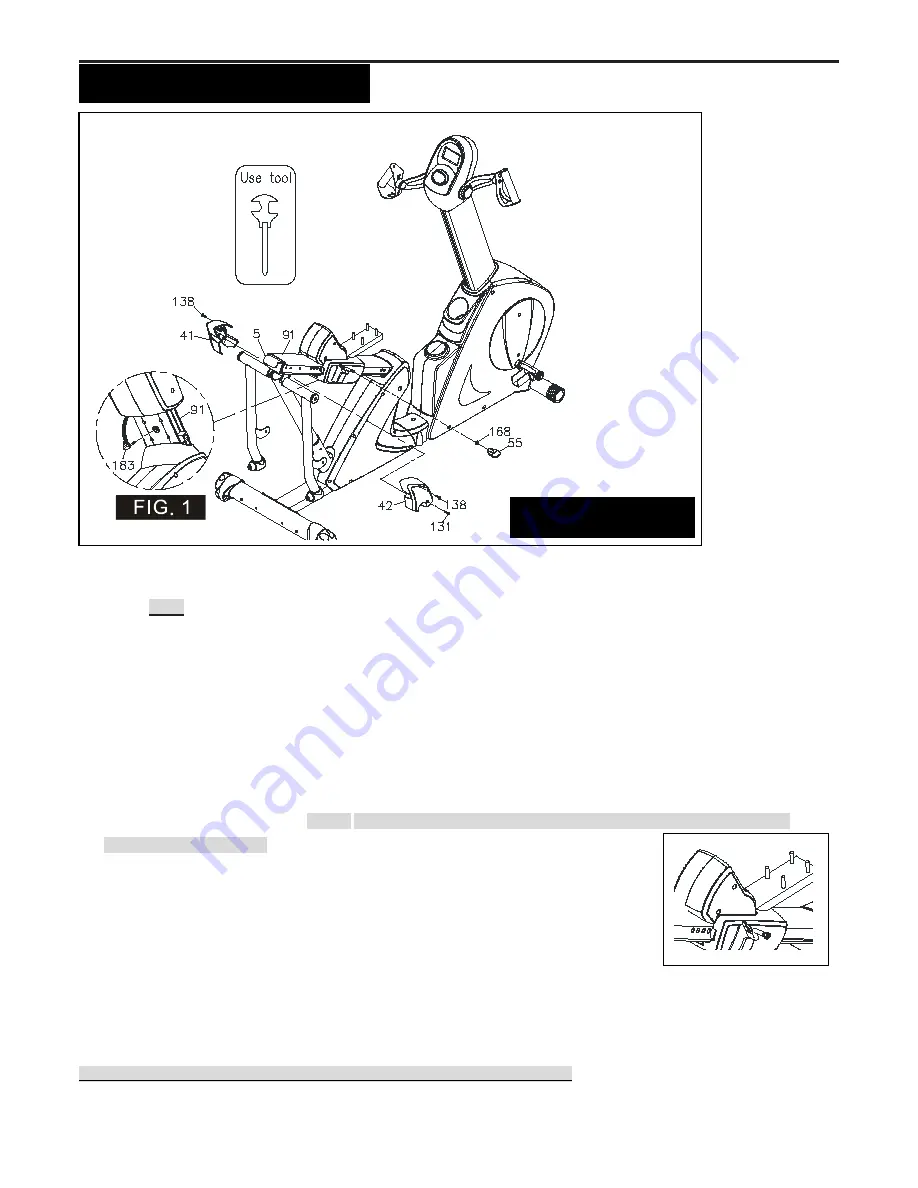
S
TEP
8
–
Short Extension Pulse Wire & Rail Decoration Assembly
a. Follow
FIG.1
to plug the
Short Extension Pulse Wire (183)
into the connector located on the front bottom side of the
Seat Rail (91).
b. Attach the
Left Rail Decoration Cover (41)
and the
Right Rail Decoration Cover (42)
to the rear side of the
Seat
Rail (91)
and secure with one
Self-Tapping Screw, Truss Head (M4x20mm)(131)
and two
Screws, Round Head
(M5xp0.8x15mm)(138).
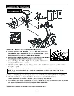
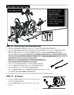
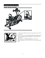
S
TEP
9
–
Adjusting Handle Assembly
a. Attach the
Adjusting Handle (55)
to the
Adjusting Handle Stand
to the proper position.
b. Secure the
Adjusting Handle (55)
by rotating the
Nut (M8)(168)
in
counterclockwise direction until completely tight
against
Adjusting Handle (55)
.
NOTE:
Please notice that the
Nut (M8)(168)
has been pre-assembled on the
Adjusting Handle Stand
.
**Make sure the above parts are tightened before moving on to the next page**
USE HARDWARE KIT
B
Summary of Contents for V2300
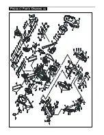
Page 24: ...24 PRODUCT PARTS DRAWING A ...
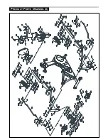
Page 25: ...25 PRODUCT PARTS DRAWING B ...


