11
“
A
SSEMBLY
I
NSTRUCTIONS
”
S
TEP
10
–
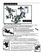
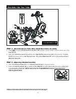
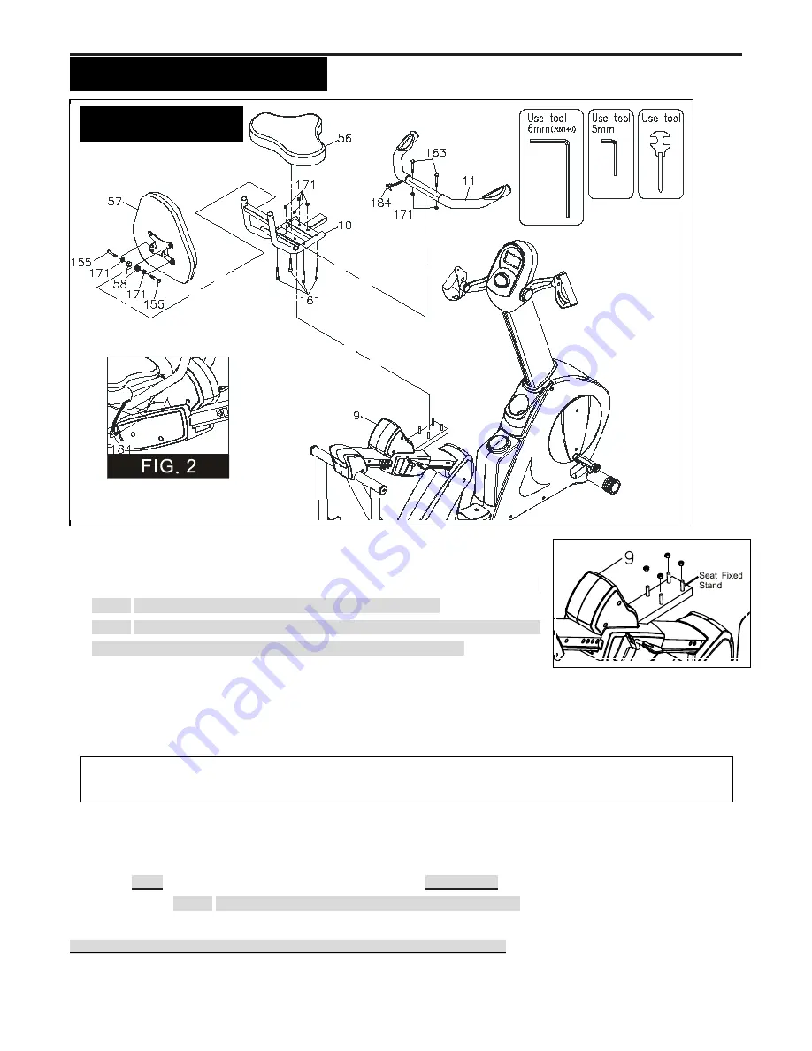
Seat and Seat Handlebar Assembly
a. Locate and secure the
Seat Handlebar (11)
on the
Seat Frame (10)
with two
Carriage Bolts (M8xp1.25x50mm)(163)
and two
Nylock Nuts (M8x1.25)(171)
.
NOTE:
Be careful not to pinch the
Pulse Sensor Wire 4 (184).
b.
NOTE:
Four
Nylock Nuts (M8x1.25)(171)
are pre-attached on the
Seat Carriage
Assembly (9)’s Seat Fixed Stand
as the figure shows on the right.
c. Remove four
Nylock Nuts (M8x1.25)(171)
from the
Seat Fixed Stand
and set
aside for the following assembly process.
d.
Attach the
Seat Frame (10)
to the
Seat Carriage Assembly (9)’s Seat Fixed Stand
and secure with
four
Nylock
Nuts (M8x1.25)(171).
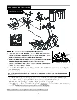
e. Place the
Seat (56)
on the
Seat Frame (10)
and secure with four
Bolts, Socket Head (M8xp1.25x40mm)(161).
f.
Attach the
Back Cushion (57)
to the
Seat Frame (10)
and secure with two
Bolt, Button Head
(M8xp1.25x40mm)(155)
, two
Nylock Nut (M8x1.25)(171)
and two
Screw Caps (58).
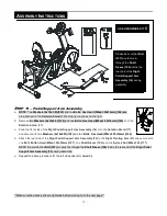
g. Follow
FIG.2
to plug the
Pulse Sensor Wire 4
(184)
into the
connector A
located on the left side of the
Seat Carriage
Assembly (9)
NOTE:
Be careful not to pinch the
Pulse Sensor Wire 4 (184).
**Make sure the above parts are tightened before moving on to the next page**
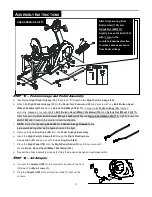
NOTE:
After assembling the
Seat Frame
, gently shake the
Seat Frame
to test and make sure the
Seat Frame
is
firmly secured
USE HARDWARE KIT
B
Summary of Contents for V2300
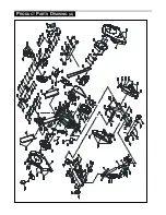
Page 24: ...24 PRODUCT PARTS DRAWING A ...
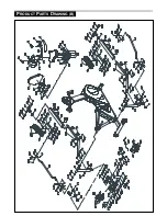
Page 25: ...25 PRODUCT PARTS DRAWING B ...


