12
“
A
SSEMBLY
I
NSTRUCTIONS
”
S
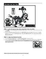
TEP
11
–
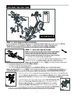
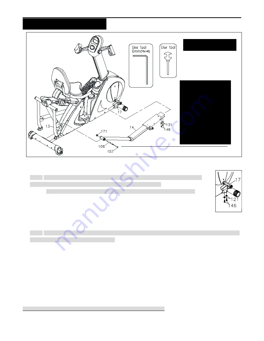
Pedal Support Arm Assembly
a.
NOTE:
Two
Washers (6x19x2.0t)(122)
and
two
Bolts, Hex Head (M8xp1.25x16mm)(146) are
pre-attached on the
Rotation Stand (17)
as the figure shows on the right
.
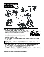
b.
Remove two
Washers (6x19x2.0t)(122)
and
two
Bolts, Hex Head (M8xp1.25x16mm)(146)
from the
Rotation Stand (17).
c. Slide the front side of the
Right Pedal Support Arm Assembly (14)
onto the
Rotation Stand (17)
and secure with
two
Washers (6x19x2.0t)(122)
and
two
Bolts, Hex Head (M8xp1.25x16mm)(146)
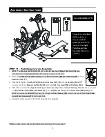
d. Attach the rear side of the
Right Pedal Support Arm Assembly (14)
to the
Right Pivoting Arm (13)
and secure with
one
Bolt, Button Head (M8xp1.25x90mm)(157)
, one
Shaft Sleeve (106)
and one
Nylock Nut (M8xp1.25)(171)
.
NOTE:
Be certain that
Bolt (157)
properly fits through the
Shaft Sleeve (106)
inside the rear end of the
Right Pedal
Support Arm Assembly (14)
during assembly.
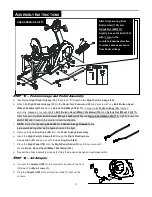
e.
Repeat the above procedure for the left side pedal arm assembly.
**Make sure the above parts are tightened before moving on to the next page**
USE HARDWARE KIT
C
Please be sure that
Bolt
(157)
would screw
through the
Shaft
Sleeve (106)
inside the
rear end of the
Right
Pedal Support Arm
Assembly (14)
during
assembly
Summary of Contents for V2300
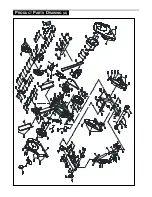
Page 24: ...24 PRODUCT PARTS DRAWING A ...
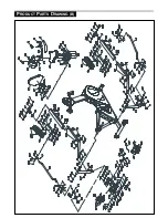
Page 25: ...25 PRODUCT PARTS DRAWING B ...


