

4
“
H
ARDWARE
I
DENTIFICATION
C
HART
”
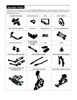
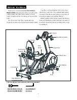
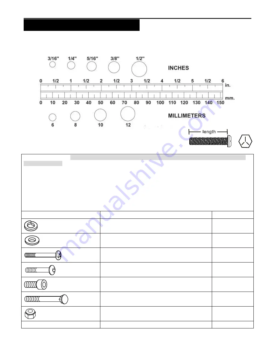
Unpack the box in a clear area. Follow the
List of Hardware Kit
below. This chart is provided to help identify the hardware
used in the assembly process. Place the washers, the end of bolts, or screws on the circles to check for the correct
diameter. Use the small scale to check the length of the bolts and screws. Do not dispose of the packing material.
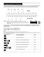
NOTICE:
The length of all bolts and screws except those with flat heads is
Measured from below the head to the end of the bolt or screw. Flat head
bolts and screws are measured from the top of the head to the end of the
bolt or screw
After unpacking the unit,
please note that there are 3 hardware bags (HARDWARE KIT A, HARDWARE KIT B and
HARDWARE KIT C)
.
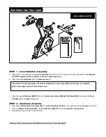
Assembly’s
Step 1 ~ 5
: Will use HARDWARE KIT
A
Assembly’s
Step 6 ~ 10
: Will use HARDWARE KIT
B
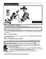
Assembly’s
Step 11 ~ 12
:
Will use HARDWARE KIT
C
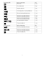
Note:
Please review the list below to ensure that the contents are present (A, B and C)
Some small parts may have been pre-attached for shipping purposes. If a part is not present in the hardware bag, check to
see if it has been pre-assembled
HARDWARE KIT
A
Part No. and Description
Q’TY
121 Lock Washer (M8)
4 pcs
124 Washer (8x23x2.0t)
2 pcs
139 Screw, Round Head (M5xp0.8x40mm)
1 pcs
154 Bolt, Button Head (M8xp1.25x30mm)
2 pcs
162 Bolt, Socket Head (M8xp1.25x70mm)
2 pcs
164 Carriage Bolt (M8xp1.25x90mm)
2 pcs
171 Nylock Nut (M8xp1.25)
2 pcs
Summary of Contents for V2300
Page 24: ...24 PRODUCT PARTS DRAWING A ...
Page 25: ...25 PRODUCT PARTS DRAWING B ...


