
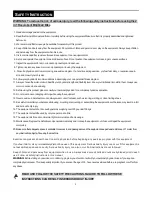

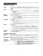
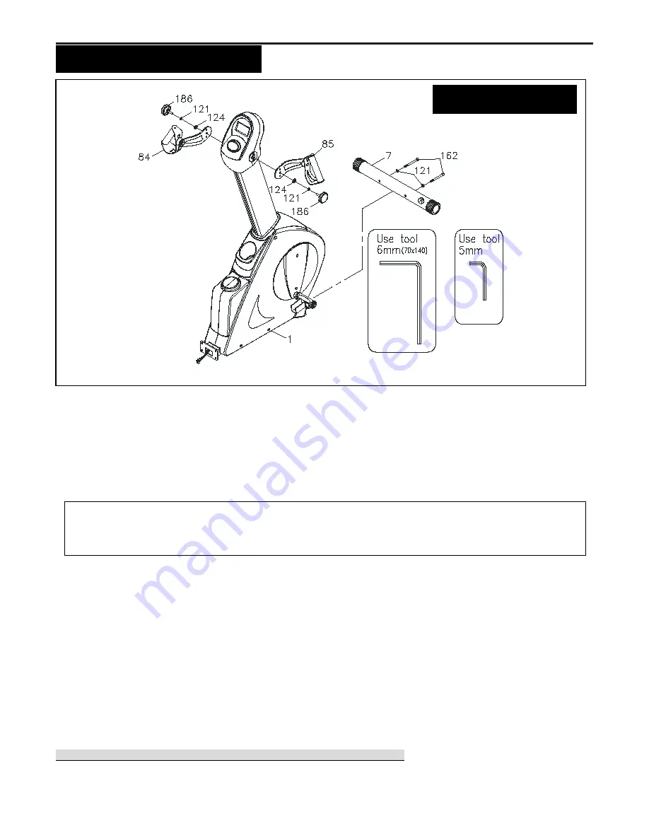
7
“
A
SSEMBLY
I
NSTRUCTIONS
”
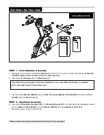
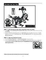
S
TEP
1
–
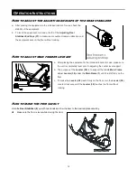
Front Stabilizer Assembly
a. Identify the correct direction of the
Front Stabilizer (7)
, there is an “R” decal on the right side of the
Front Stabilizer
(7)(NOTE: Right and left orientation is from the seated position).
b. Attach the
Front Stabilizer (7)
to the
Main Frame (1).
c. Attach
two
Lock Washers (M8)(121)
and two
Bolts, Socket Head (M8xp1.25x70mm)(162)
that secure the
Front
Stabilizer (7)
to the
Main Frame (1).
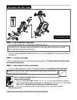
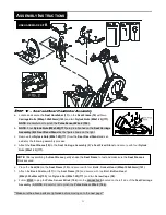
S
TEP
2
–
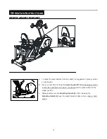
Handlebar Assembly
a. Attach the
Left Handlebar Assembly (85)
to the
Mounting Bracket (83)
on the right side of the
Console
and secure
with one
Washer (8x23x2.0t)(124)
, one
Lock Washer (M8)(121)
and one
Adjustment Knob (186).
b. Repeat the above process for the left side.
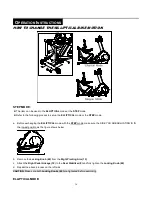
**Make sure the above parts are tightened before moving on to the next page**
“
Helpful Hint:
Only hand tighten the bolts and fasteners in each step. Wait until the step is completed
before fully tightening the bolts and fasteners”
USE HARDWARE KIT
A
Summary of Contents for V2300
Page 24: ...24 PRODUCT PARTS DRAWING A ...
Page 25: ...25 PRODUCT PARTS DRAWING B ...


