© SMP (PLAYGROUNDS) LTD, TEN ACRE LANE, THORPE, EGHAM, SURREY, TW20 8RJ
POLYNESIA SPRINGERS
Appendix B Page 1
Appendix B: SPCAR FOOTREST REPLACEMENT
The assembly below is for the replacement of an existing cylindrical footrest with a new headed type footrest. The
parts list includes all the components required to complete the assembly.
1
FOOTREST ASSEMBLY
PARTS LIST
i)
Dismantle the SPCAR springer body. See Section 1-3 & Appendix A 2.2 Installation & Assy Procedures and
reverse the procedure.
ii)
Remove Locator from rectangular hole in Front Profile and discard.
iii)
Open out the counterbored hole in both Inner Body Profiles only by drilling through with a Ø20mm drill. (This
allows access to the Front Profile register slot for the Locator).
iv)
Re-assemble springer body. See Section 1-3 & Appendix A 2.2 Installation & Assy Procedures.
v)
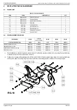
Place Locator (Item 4.3) through hole in Inner Body Profiles and Front Profile. Slide handles (item 4.1) onto
locator (item 4.3) and secure with M10 x 80 Hex head bolts (item 4.5) and M10 washers (item 4.4). (Apply
Aradite or similar to bolt threads.) Tighten to a torque setting of 24-27 Nm (18-20 lbf ft). (FIG.11)
NOTE: When assembling the Hex head bolts, one bolt should be screwed in for 10 revolutions before
assembling the second bolt to the recommended torque settings. This ensures that the locator is
central about the front Profile thickness.
vi)
Position handle caps (item 1.2) in end of handles and tap into position, ensuring they finish flush with the
surrounding plastic surface with no sharp edges..
ITEM
CODE
DESCRIPTION
QTY.
4.1
86012001
HANDLE
2
4.2
86012002
HANDLE CAP - (DOMED HEAD)
2
4.3
86012005
LOCATOR
1
4.4
10291000
WASHER-PLAIN M10
2
4.5
10251080
HEX HD. BOLT M10 X 80
2
4.6
19028651
PLASTIC CAP - (FLAT STEPPED HEAD)
12
FIG.11
4.2
4.5
4.1
4.4
4.3
FRONT PROFILE
INNER BODY PROFILE
ISSUE N
Summary of Contents for SPBIK
Page 2: ...INTENTIONALLY LEFT BLANK...


