© SMP (PLAYGROUNDS) LTD, TEN ACRE LANE, THORPE, EGHAM, SURREY, TW20 8RJ
POLYNESIA SPRINGERS
Section 1 Page 1
1
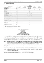
SPECIFICATIONS
* The second figure refers to loose-fill installations
*NOTE:
All dimensions in metres.
Concrete mix is recommended at:
1 part cement;
2 parts sand;
4 parts aggregate;
by volume with 20mm aggregate
(20 N/mm
2
min compressive strength )
The freefall height of the springers is less than 0.6m and therefore in accordance with EN1176 it does not strictly
require impact absorbing surfacing which has been fully tested to EN1177. However, if they are being installed on
hard surfaces such as concrete or tarmac, we recommend that a minimum surfacing area as indicated in the chart
above is specified to enhance the safety of its provision. If they are being provided on a grass surface, a suitable
level of maintenance will be required to ensure the impact attenuation properties are not significantly reduced.
NOTE: FIGS 1 & 2
. Generally, it is recommended that loose fill surfaces are installed to a depth of 300mm. However
with certain loose fill materials, a greater depth may be required. This will need to be determined by allowing
100mm for dispersal in addition to the thickness required to achieve the required critical fall height.
Constructional Space (shown in the above table) is the approximate working area required to layout and assemble
the equipment.
For the safe operation of this equipment it must be installed on horizontal ground with the required minimum space.
Tools:
Plumbline, 5m tape measure, Spirit level, Torque wrench, 5/16" Socket, 2-off 17mm AF Sockets & Drivers,
M10 Torx tool (Supplied with unit).
Minimum Personal Protective Equipment:
Gloves, Armoured boots & Protective goggles.
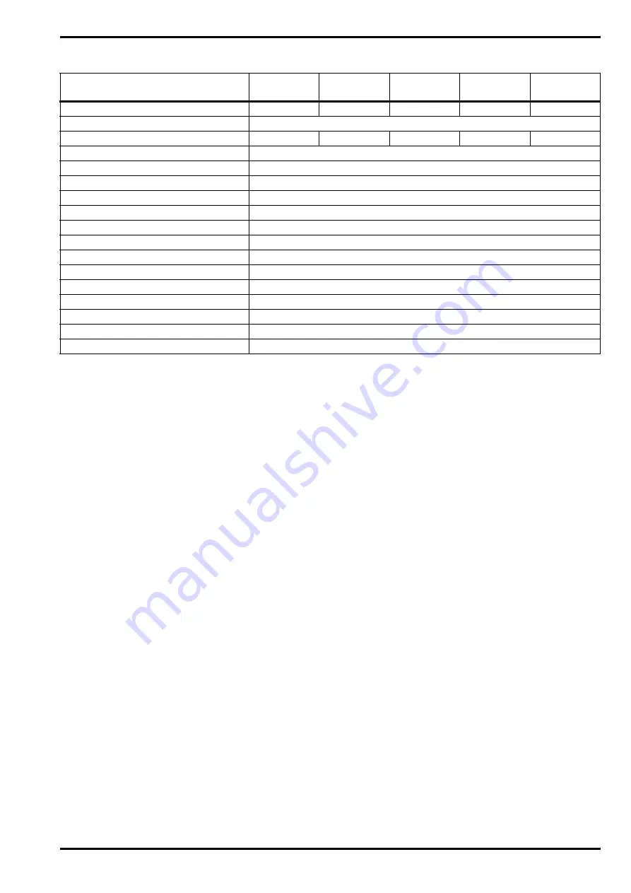
REFERENCE
SPCAT
SPBIK
SPCAR
(DISCONTINUED)
SPHIP
SPFIS
OVERALL HEIGHT (H)
m
0.71/.61*
0.72/0.62*
0.73/0.63*
0.70/0.60*
0.71/0.61*
SEAT HEIGHT (h)
m
0.50/0.40*
LENGTH (L)
m
0.93
1.00
1.21
1.06
1.01
WIDTH (W)
m
0.34
WEIGHT
kg
36
HEAVIEST PART
kg
23
LARGEST PART L x W x H
m
0.60 x 0.60 x 0.50
CONCRETE
m
3
0.05/0.07 *
MINIMUM SPACE L x W x H
m
3.40 x 2.75 x 3.00
MAXIMUM FREEFALL HEIGHT
m
0.50 / 0.40*
FALLING SPACE AREA
m
2
6
IMPACT AREA (WET POUR)
m
2
5
RUBBER TILES 1m x 1m
5
LOOSE FILL AREA (SAND/BARK)
m
2
7
MANHOURS
hr
2
MANPOWER
2
CONSTRUCTIONAL SPACE
m
3 x 3
ISSUE N
Summary of Contents for SPBIK
Page 2: ...INTENTIONALLY LEFT BLANK...


