© SMP (PLAYGROUNDS) LTD, TEN ACRE LANE, THORPE, EGHAM, SURREY, TW20 8RJ
POLYNESIA SPRINGERS
Section 1 Page 3
3
INSTALLATION & ASSY PROCEDURES
PRE-INSTALLATION INSPECTION :
Inspect all parts for damage (that may have occurred during transportation &
storage). Finish Coatings, if found to be damaged these should be made good
before erection. Any damaged or missing parts must be replaced.
i)
Warn the public of the risk of injury, by placing signs and fencing the
surrounding area, before commencing installation.
ii)
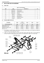
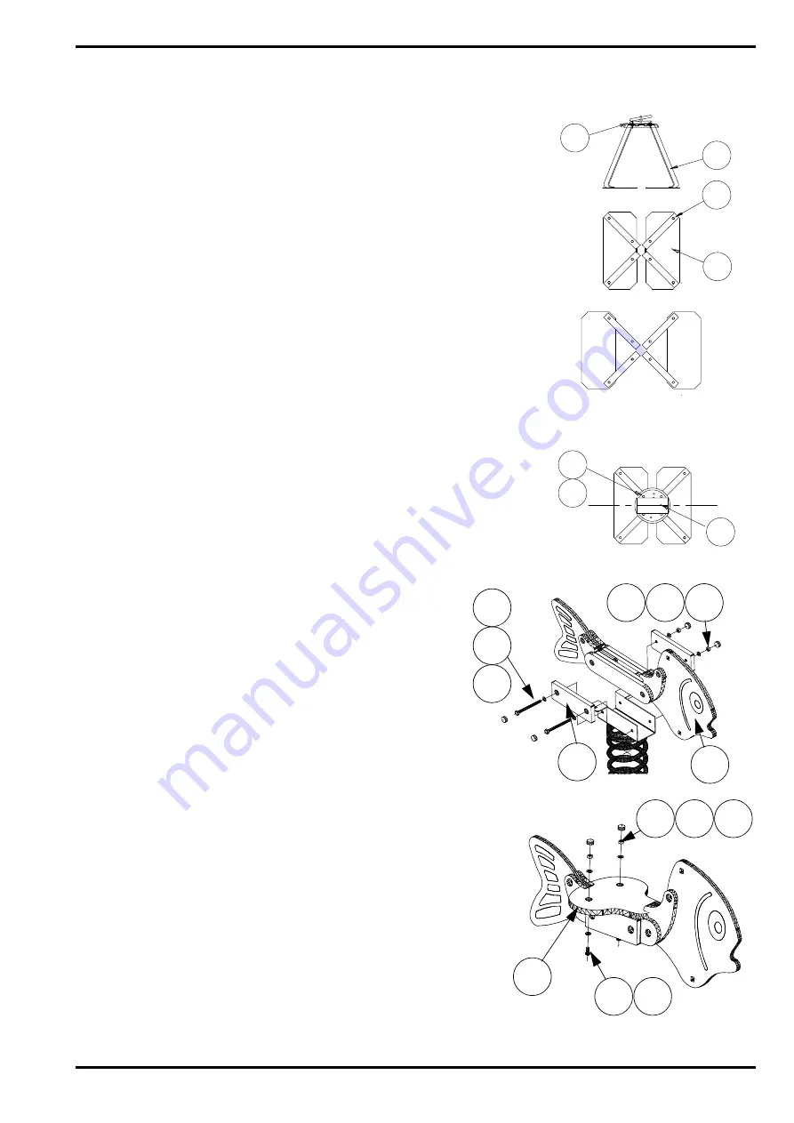
Note if the installation is 'standard' or 'loose fill',then assemble the base
supports (1.3) to the base plates (1.4) the appropriate way round using 4-
off Torx bolts (1.9) and fully secure.(Fig 3).
iii)
Align the base sub-assy onto the spring sub-assy (1.2) in the angular
position shown in Fig 4.
iv)
Assemble the spring sub-assy onto the base sub-assy using 4-off Torx
bolts (1.9) and washers (1.6).Tighten Torx bolts to a torque setting
between 40-43 Nm (30-32 lbf ft). (Fig 4).
v)
Position the unit, mark out the foundation holes (Figs 1 & 2). Place the
unit to one side and excavate the holes. If applicable refer to the site
plan for unit location.
vi)
Place the unit into the hole, then level and square the unit. Pour
concrete into the hole to a minimum thickness of 100mm (Figs 1 & 2).
Allow to cure before continuing (Recommended initial curing time is 48
hours minimum).
vii) Backfill the hole with earth to the required level, taking into
account any 'impact absorbing surfacing requirements'
(Figs 1 & 2). Refer to separate instructions if applicable.
viii) Place body sub-assy (1.1) onto spring & base sub-assy.
Align holes. Place bolt (1.5) thro' plain washer (1.6) and
outer poly cover with c'bore facing outermost (1.11) & feed
thro' spring sub assy & body sub assy. Fit washer (1.6) &
nut (1.7).Tighten bolts to a torque setting between 24-27
Nm (18-20 lbf ft).(Fig 5).
ix)
Place the seat (1.12) into position, tucking front of seat into
slot on profile. From underside, place bolt (1.10) thro' plain
washer (1.6) & feed thro' holes in spring sub-assy & seat holes.
Fit washer (1.6) and nut (1.7).Tighten bolts to a torque setting
between 24-27 Nm (18-20 lbf ft).(Fig 6).
x)
Tap plastic cap (1.8) into recess on both sides of body & seat top
face, ensuring they finish flush with the surrounding plastic
surface with no sharp edges.
1.2
1.3
1.9
1.4
STANDARD INSTALLATION
LOOSE FILL INSTALLATION
Fig 3
¤
¤
1.6
1.9
Fig 4
PROFILE
1.2
FIG.5
1.6 1.7 1.8
1.1
1.8
1.6
1.11
1.5
1.6
1.8
1.7
1.6
1.10
1.12
ISSUE N
FIG.6
Summary of Contents for SPBIK
Page 2: ...INTENTIONALLY LEFT BLANK...


