Power Pacs:
This lift is powered by a 12VDC removable power pac located at the back of the lift. The power pac fits either way in
the lift and charger box. This is to make it easy to remove and replace the power pac.
NOTE: Power pac removal is your emergency stop feature.
(Figure A)
The lift has a built
-
in power pac indicator which illuminates when the power pac is about 60% discharged. This would
be the best time to replace the power pac with one that is fully charged. If the power pac indicator is solid red during
rotation of the actuator, this means there is approximately 20% capacity left in the power pac. The power pac must be
charged as soon as possible.
Once the power pac is inserted into the charging unit, the charge light on the charging unit comes on. Make sure this
yellow light comes on to assure your power pac is charging. Once the power pac is fully charged, the light will shut off.
The charger is fully automatic and will quit charging when the power pac reaches a full charge. You will not damage the
power pac or charger if the power pac is left on the charger. The power pac life can vary depending on how many
charging cycles the power pac has undergone or if the power pac was improperly stored discharged for a long period of
time. A typical life cycle is between 1000
-
1200 cycles from full to empty. (see charging procedure page 12) (Figure B)
Switches:
The lift is operated by switches located at the tips of the handles. This allows proper ergonomics by keeping the hands
on the handles while operating the lift and maneuvering it at the same time. The optional hand control provides a second
source to operate the lift. This allows the operator to be next to the person being transferred and to operate the lift at the
same time. It also aids as a back
-
up source to operate the lift. (Figure C)
Emergency Down Feature:
If your lift is equipped with the emergency down feature, engage the rocker switch (under power box) to lower the lift.
This is to be used in an emergency only, service may be needed. (Figure D)
Power Failure:
If for any reason the lift would stop in mid travel, the first thing to check is the circuit breaker located on the power pac
box. If the breaker has popped out, simply press it back in and try lifting. (Figure E) If the problem is not the breaker,
and you cannot lower the patient/resident by the switch on the handle or the remote control, you must use the emergency
down located under the power box. (Figure D) Another option is the manual safety override
5/16”
x
3/8”
bit provided
with the lift.
Manual Down Operation:
As a last option to operate the lift manually, remove the plastic plug at the top of the mast and use the 5/16" hex driver
supplied with the lift, and a 3/8" socket and ratchet with extension. Insert the hex driver into the hex head at the top of
the ball screw and simply turn in the desired rotation.
Width Adjustment:
The leg adjuster opens and closes the legs of the lift. By pulling back, this allows you to rotate the handle back and forth.
Keep the handle pulled back while rotating to keep the leg adjuster handle from rubbing on the notch plate. This process
enables the lift to be narrowed to go through doorways and widened to go around a wheel chair or lounge chair.
(Figure G)
Wheel Locks:
The brakes are located on the rear wheels. Press the tab with your foot to lock the wheel and the swivel. Press the upper
portion of the tab to release the brakes.
Mechanical Operation
(Operation Corresponds with the View on Page 4)
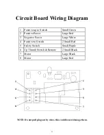
Figure A
Figure B
Figure C
Figure D
Figure E
Figure G
10


