14
of
84
8.3 Baseframe Location
IMPORTANT: DO NOT CUT THE
SHIPPING STRAPS HOLDING
EACH SCISSOR ASSEMBLY
TOGETHER UNTIL
INSTRUCTED TO DO SO.
1. With reference to
Figure 3
,
the installer should locate the
most suitable location in the
shop for the lift.
2. Snap a chalk line for the
centerline of the lift ensuring
that it matches the centerline of
the bay door.
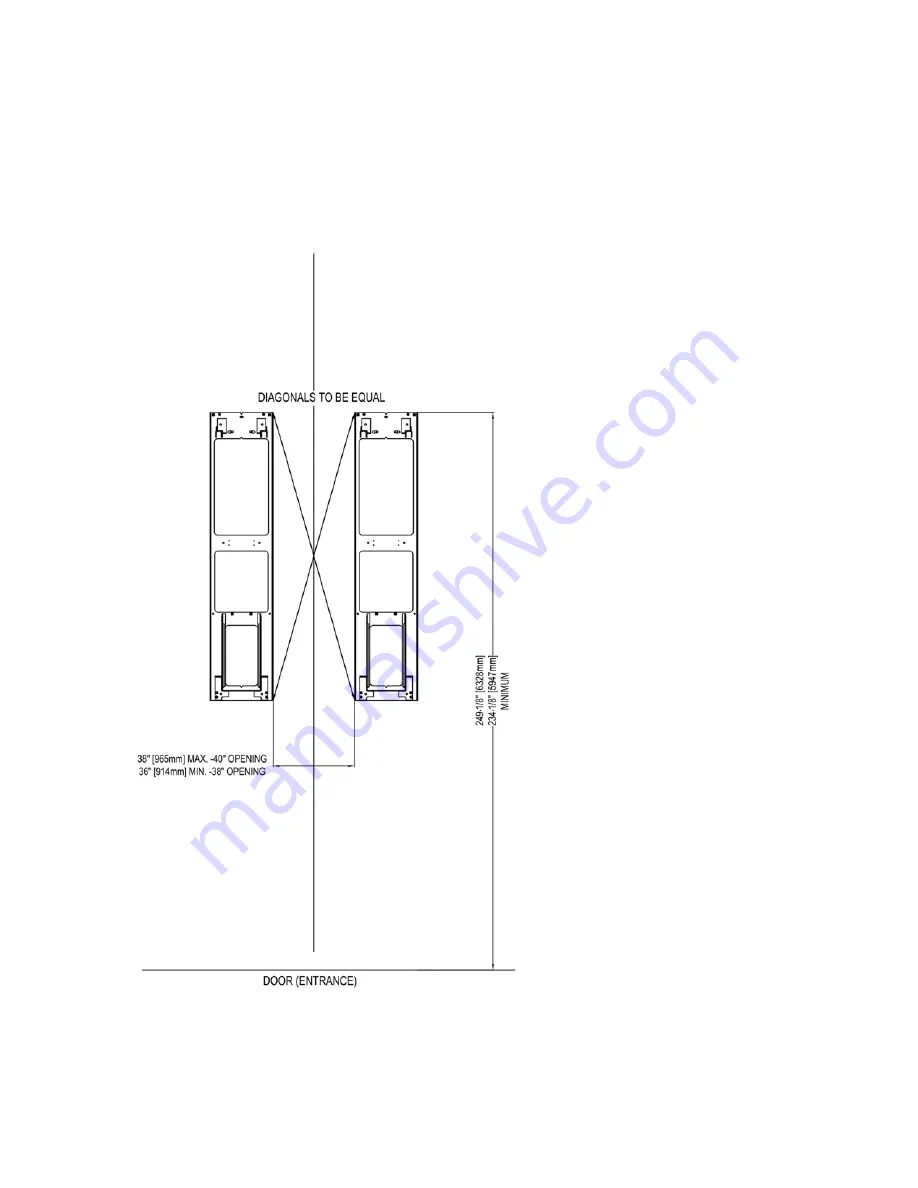
3. Measure and snap two (2)
parallel chalk lines on either
side the centerline for the
inside edges of the
baseframes. Refer to
Figure
4
for the dimensions
necessary to provide the
desired width between the
two runways. A distance of
36" (914mm) between the
baseframes will provide the
standard width of 38”
(965mm) between the inside
of the runways.
4. Measure and snap a chalk
line parallel to the shop door
for the front of the
baseframes, a minimum
distance of 249 1/8”
(6328mm) for the standard
length lift is recommended.
For short length lifts, use a
minimum of 234-1/8"
(5947mm).
5. Before proceeding, ensure
that once the runways are
installed adequate workspace
will remain in front of the lift. Refer to the minimum requirements listed in the installation and
operation manual of any alignment equipment as needed.
Figure 4 - Baseframe Locations
Summary of Contents for EELR587A
Page 7: ...7 of 84 3 0 SAFETY WARNING DECALS...
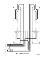
Page 18: ...18 of 84 Figure 8 Hydraulic Connections...
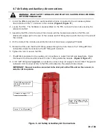
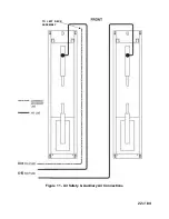
Page 22: ...22 of 84 TO LEFT DECK ASSEMBLY Figure 11 Air Safety Auxiliary Air Connections...
Page 26: ...26 of 84 Figure 15b Optional LED Driver Box Circuit Connections...
Page 35: ...35 of 84 Figure 28 Filler Angle Installation...
Page 64: ...64 of 84 20 0 ACCESSORY ASSEMBLY 20 1 Front Turnplate...
Page 67: ...67 of 84 20 3 Airline Routing for Locking Turnplates and Rear Slip Plates...
Page 79: ...79 of 84 22 0 POWERPACK ASSEMBLY 22 1 Powerpack Assembly EAA0441V72A...


