24
of
84
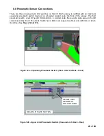
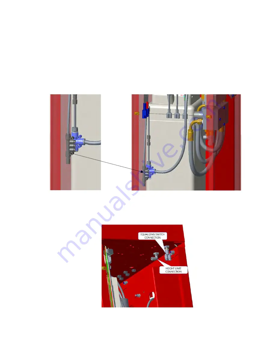
1. Route two red Ø4mm air lines labeled with “EQ SUPPLY” and “LMT SUPPLY” from left side
baseframe and one red Ø4mm air lines labeled with “EQ SUPPLY” from right side baseframe
to console and connect them to the “5 PORTS MANIFOLD” fitting in console (
Figure 13
).
2. Route two blue Ø4mm air lines labeled with “EQ RETURN” from left side and right side
baseframe to console and connect them to a union ‘Y’ fitting in the console (
Figure 14
).
3. Route one blue Ø4mm air lines labeled with “LMT RETURN” from left side baseframe to
console and connect to the pressure switch fitting in the console (
Figure 14
).
Figure 13 - Pneumatic Switch Supply Line Connections (Console)
Figure 14 - Pneumatic Switch Return Line Connections (Console)
Summary of Contents for EELR587A
Page 7: ...7 of 84 3 0 SAFETY WARNING DECALS...
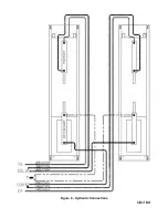
Page 18: ...18 of 84 Figure 8 Hydraulic Connections...
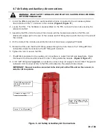
Page 22: ...22 of 84 TO LEFT DECK ASSEMBLY Figure 11 Air Safety Auxiliary Air Connections...
Page 26: ...26 of 84 Figure 15b Optional LED Driver Box Circuit Connections...
Page 35: ...35 of 84 Figure 28 Filler Angle Installation...
Page 64: ...64 of 84 20 0 ACCESSORY ASSEMBLY 20 1 Front Turnplate...
Page 67: ...67 of 84 20 3 Airline Routing for Locking Turnplates and Rear Slip Plates...
Page 79: ...79 of 84 22 0 POWERPACK ASSEMBLY 22 1 Powerpack Assembly EAA0441V72A...


