27
of
84
8.10 Initial Operation
1. Add hydraulic fluid to reservoir (ISO 32 10wt). Oil capacity for the lift is approximately 6 gallons.
IMPORTANT: Shop air must be connected to the inlet port at the FRL unit in the console, in
order for lift to operate.
2. Raise lift to 2 ft, lower and repeat 3 to 4 times, using “UP” and “DOWN” controls on the front of the
console.
* During this stage the lift is not yet full of oil. During the following steps, one side of the lift
may raise higher than the other.
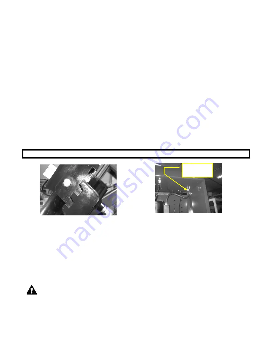
3. Using the “BYPASS” button inside the console see
Figure 17
, start raising the lift to the last lock
position as shown in
Figure 16
.
Monitor the fluid level during this procedure. At approximately half way, add 10 liters of oil to the
reservoir. Continue to raise the lift.
NOTE: Ensure the gauges inside the console are monitored and pressure does not reach
1000 psi. If 1000 psi is reached, lower the lift onto the locks to relieve the pressure.
Continue to raise the lift until both sides of the lift are on the last lock position. (Figure 15)
IMPORTANT:
The unit must be on the last locking position to bleed the lift.
Figure 16-Safety lock position for bleeding.
Figure 17- Location of bypass button.
4.
BLEED THE SYSTEM:
Once the lift is placed on the last safety position, remove the polytube
return lines, at the Tee fitting (
Figure 7
) and place them into a funnel over the reservoir. Press the
bypass button until a clear stream of oil is flowing from the return lines. Release the bypass button
and wait for 5 -10 seconds and continue to bleed. Repeat this “wait and bleed” procedure 5 times
or until air is no longer visible in the return lines. Connect polytube lines back to the Tee fitting.
5.
RELEASE THE SAFETY LOCKS
: Place a rag or drip pan directly under the secondary cylinder
and remove the 90 deg. push lock fittings on the top of the secondary cylinders (see
Figure 18
).
Cap the port using the plugs provided (see
Figure 19
).
Holding the air safety release button on the console, raise the lift using the “BYPASS” button
until the safety locks disengage.
DO NOT BUILD PRESSURE OVER 1000 PSI.
6.
Lower the lift to the next safety lock. Remove the plugs and reinstall the 90 deg push lock fittings.
Lower the lift to a comfortable working height and continue the installation.
Bypass
button
Summary of Contents for EELR587A
Page 7: ...7 of 84 3 0 SAFETY WARNING DECALS...
Page 18: ...18 of 84 Figure 8 Hydraulic Connections...
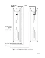
Page 22: ...22 of 84 TO LEFT DECK ASSEMBLY Figure 11 Air Safety Auxiliary Air Connections...
Page 26: ...26 of 84 Figure 15b Optional LED Driver Box Circuit Connections...
Page 35: ...35 of 84 Figure 28 Filler Angle Installation...
Page 64: ...64 of 84 20 0 ACCESSORY ASSEMBLY 20 1 Front Turnplate...
Page 67: ...67 of 84 20 3 Airline Routing for Locking Turnplates and Rear Slip Plates...
Page 79: ...79 of 84 22 0 POWERPACK ASSEMBLY 22 1 Powerpack Assembly EAA0441V72A...


