28
of
84
PLUG
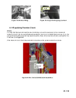
Figure 18- Remove fitting.
Figure 19- Cap port using plug provided.
8.11 Equalizing Function Check
Check:
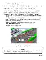
To verify that the pneumatic switches are functioning, remove the rear panel on the console and
locate the five (5) Din Connector/Solenoid assemblies; (four (4) on manifold block and one (1) on the
pump). When the lift reaches its fully lowered position, these din connectors will emit a red light for 3 to
5 seconds. (see
Figure 20
).
If this does not occur, check the pneumatic connections at the sensors and at the console.
Figure 20 - Din Connector/Solenoid assemblies.
Summary of Contents for EELR587A
Page 7: ...7 of 84 3 0 SAFETY WARNING DECALS...
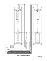
Page 18: ...18 of 84 Figure 8 Hydraulic Connections...
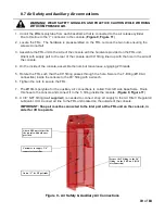
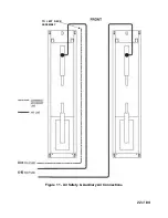
Page 22: ...22 of 84 TO LEFT DECK ASSEMBLY Figure 11 Air Safety Auxiliary Air Connections...
Page 26: ...26 of 84 Figure 15b Optional LED Driver Box Circuit Connections...
Page 35: ...35 of 84 Figure 28 Filler Angle Installation...
Page 64: ...64 of 84 20 0 ACCESSORY ASSEMBLY 20 1 Front Turnplate...
Page 67: ...67 of 84 20 3 Airline Routing for Locking Turnplates and Rear Slip Plates...
Page 79: ...79 of 84 22 0 POWERPACK ASSEMBLY 22 1 Powerpack Assembly EAA0441V72A...


