38
of
84
10.0 LOCKING FRONT TURNPLATES & REAR SLIP PLATES (OPTIONAL)
10.1 Installation of Front Turnplates
Avoid inserting fingers in the front alignment pan cut-out, if position of the turnplate assembly
exposes such openings.
Ensure that air supply to the lift is turned off and no person is operating on the console during
maintenance of clamping elements of the locking system.
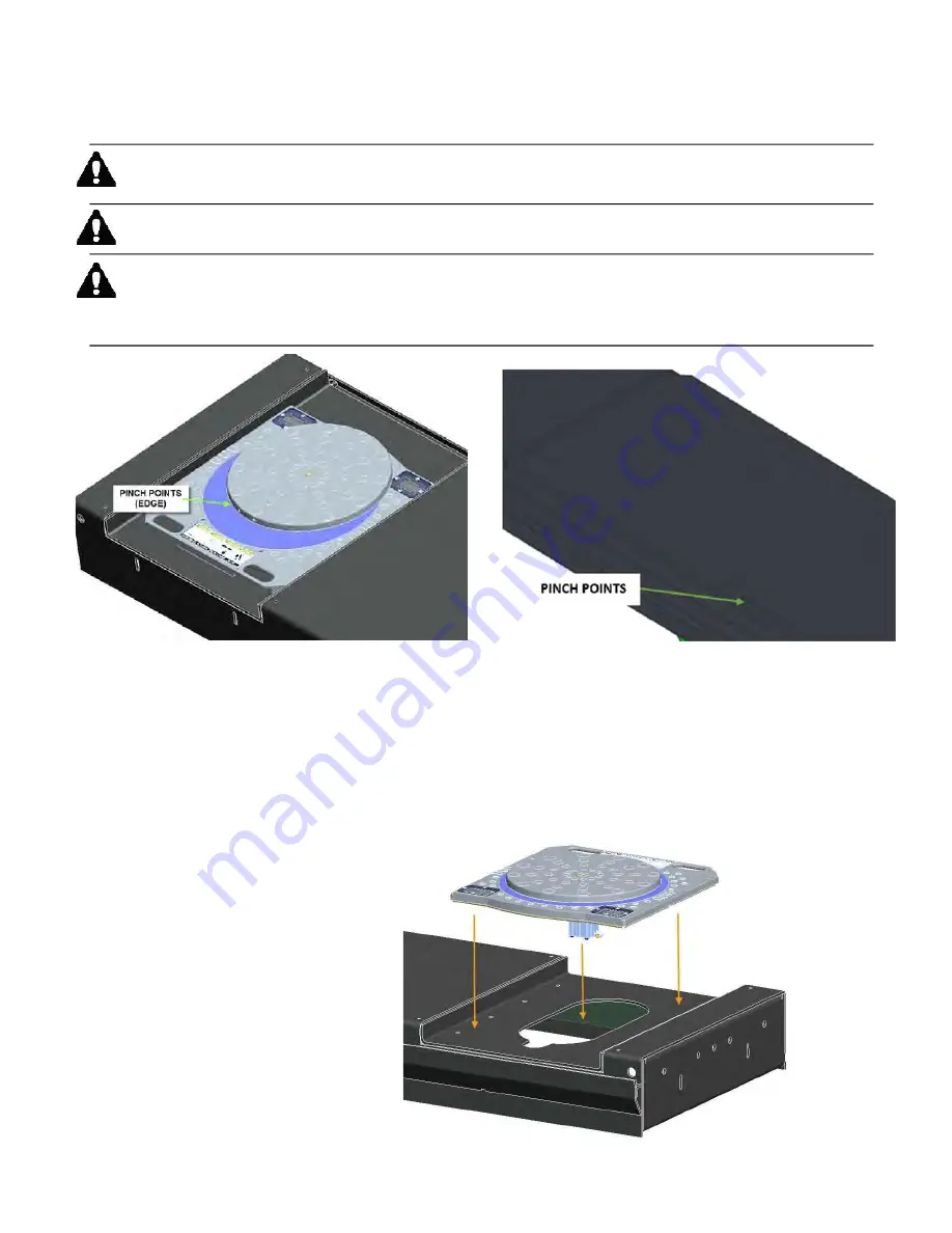
During normal use, the front turnplates and rear slip plates may move rapidly, when locking
system is activated. This creates pinch points for your fingers or hands. Keep hands clear of
these pinch points when lift air supply is connected. No person shall operate console while
maintenance or inspection of the slip plates is in process.
Figure 31 - Pinch Points
1.
Lower lift to a comfort height.
2. Place each front turnplate assembly, one by one, on the front alignment pan on runway. Moving
handles of the turnplates should be oriented to the outside of lift, shown below. See
Figure 32.
3. Verify that the turnplate assembly is completely seated in the front alignment pan. Gently slide
each turnplate in the alignment pan, left and right, to verify that they can be positioned for
different car widths. Do not hit plastic locking ring forcefully against the edges of the cut-out in
the front alignment pan.
Figure 32 - Position Turnplates
Summary of Contents for EELR587A
Page 7: ...7 of 84 3 0 SAFETY WARNING DECALS...
Page 18: ...18 of 84 Figure 8 Hydraulic Connections...
Page 22: ...22 of 84 TO LEFT DECK ASSEMBLY Figure 11 Air Safety Auxiliary Air Connections...
Page 26: ...26 of 84 Figure 15b Optional LED Driver Box Circuit Connections...
Page 35: ...35 of 84 Figure 28 Filler Angle Installation...
Page 64: ...64 of 84 20 0 ACCESSORY ASSEMBLY 20 1 Front Turnplate...
Page 67: ...67 of 84 20 3 Airline Routing for Locking Turnplates and Rear Slip Plates...
Page 79: ...79 of 84 22 0 POWERPACK ASSEMBLY 22 1 Powerpack Assembly EAA0441V72A...


