14
Snap-On EEWH329A
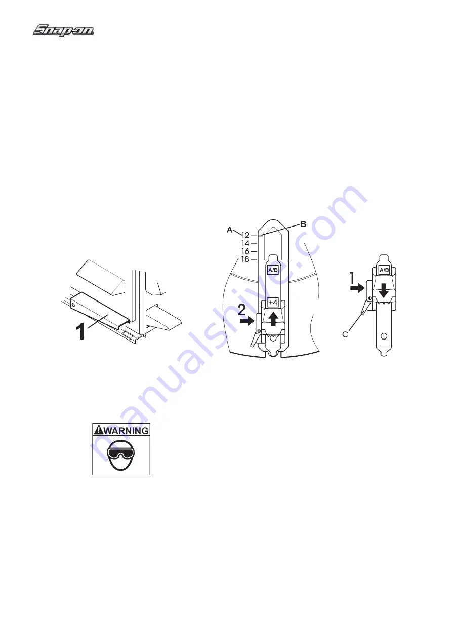
3.1 PRESETTING OF CLAMPING JAWS
MAKE SURE ALL FOUR CLAMPING JAWS ARE
POSITIONED IDENTICALLY (FIG. 3.1-1, ITEMS
1 OR 2). OTHERWISE THE RIM MIGHT NOT BE
CLAMPED PROPERLY, COME OFF THE CHUCK
AND HURT THE OPERATOR!
A
Depress fi rst pedal from the left smoothly up to the
centre position. If the pedal is released the clamping
jaws stop in the position they have reached at the time.
B
Set the clamping diameter according to the
dimensions of the rim.
Rim diameters are shown in inches on the turntable
(
A
, Fig. 3.1-1). The setting diameter (scale on the jaw
-
B
- corresponding to the scale on the turntable -
A
-)
depends on the position of the jaws (
1
, or
2
, Fig. 3.1-1).
1115
Fig. 3.1-1
C
To reposition the jaws free the lock pin by applying
pressure on the lever (
C
) on the right side of each
jaw. Slide the jaws towards the required position and
release the lever: make sure the jaw is now locked
fi rmly. Repeat the procedure on all the turntable jaws.
With the jaws in position
1
(1, Fig. 3.1-1), the operative
diameter is exactly as indicated by the scale (
A-B
) on
the turntable.
With the jaws in position
2
(2, Fig. 3.1-1), add 4” to the
value represented by the scales to obtain the effective
setting diameter.
D
Position wheel and press it down by hand on the
turntable.
E
Depress pedal through the fi rst position and release.
The wheel is clamped.
E
Turn Swing Arm Adjustment Knob
(4)
for
positioning mount/demount head slightly away
from rim diameter.
F
Lift upward on the restraint-positioning knob
(2)
to
position over tire/wheel assembly for infl ation, at
the same time push down on the Anti-rotation Lock
Arm to release lock.
(1)
You may now swing the
safety restraint arm to position on the center of the
wheel. Lower the restraint until the rubber pad on
the restraint disc is resting on the rim center. The
SRA is a gravity lock that will automatically lock if
any force other than the restraint position knob is
lifted. You are now ready for the infl ation process.
NOTE:
the turntable infl ation will not function until the
safety arm is centered over the turntable.
G
Press bead-seater pedal on left side of the machine
(5, Fig. 3.0-1 /
1, Fig. 3.0-2) halfway down: This
will allow activate the tire infl ation line.
Figure 3.0-2
H
Press bead-seater pedal (1, Fig. 3.0-2) swiftly all
the way down to get air blast from the infl ator jets
in the clamping jaws. Air simultaneously comes
out of infl ator hose.
WARNING!!
WHEN OPERATING THE BEAD SEATER IT IS
MANDATORY TO WEAR SAFETY GLASSES TO
PROTECT EYES.
Summary of Contents for EEWH329A
Page 25: ...25 Snap On EEWH329A Blank Page ...
Page 28: ...28 Snap On EEWH329A ...
Page 51: ...51 Snap On EEWH329A Page blanche ...
Page 54: ...54 Snap On EEWH329A ...


